Forum Replies Created
-
AuthorPosts
-
cameronParticipant
Flexible meshes – triangular/rectangular elements that can vary in size and shape throughout the model boundaries. These models are also known as finite element or finite volume. ADH, SRH-2D, RiverFlow2D, RMA2, FESWMS, TUFLOW FV and the DHI products are examples of this type of model. The elevations for the model are usually based on the nodes of the triangles.
Rectangular grids – these models can only have one cell size for the entire grid, but some models can have smaller grids placed inside the larger grids. These models are usually reffered to as finite difference models. These models include TUFLOW Classic (XP-2D), FLO-2D, and DHI products. The elevations for these models is usually an average over each cell and are represented in the cell center. Most models have added features such as levees/ridge lines, and 1D channels to allow them to have larger cell sizes and still pick up all of the detail.
Rectangular grid models have been known to be more stable than the flexible mesh models in the past due to wetting and drying, but more recent flexible mesh models can be just as stable. Another thing to look at is whether a model is uses an implicit or explicit solver which may control how fast a model will run.
HEC-RAS 2D is different as each element is like a mini storage area and has a elevation/volume relationship and that each face acts like a cross-section.
When to choose one over the other – it depends on the type of project. If you are trying to determine pier scour, flows around abutments, or mostly riverine then a flexible mesh model is probably best. I would also use a flexible mesh if I have a very large area and need fine detail only in certain parts as this can allow you to have a lot less number of total elements (speeds up runtime).
If you are trying to model overland flow and generate floodplains grid models may be better as they usually offer more features they may help model hydraulic structures such as culverts.
cameronParticipantUsing the 1D/2D iteration options can help (page 91-92 of user 2D user manual) has some good information working with 1D and 2D connections.
You may need to add more elements in the vicinity of the 1D structure. If the model is going unstable right away you may need to do a hotstart/warm up in the 2D domain.
Included in one of the test cases that comes with the data is an example of a 1D structure in a 2D domain.
I would also check what time step you are using as this has a big impact on if it is stable or not.
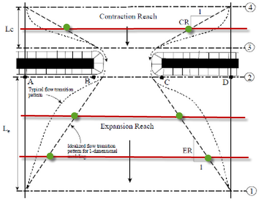
cameronParticipantCross-sections 1 and 4 are supposed to be at the beginning/end of contraction/expansion and cross-sections 1 to 4 represent the minimum number of cross-sections required to model a structure. It is very common to have more cross-sections than 4, I do it all the time. The table/figure is just telling you that if you have cross-sections between 1 and 2 or 3 and 4 (red lines), you need to apply ineffective flow areas to them based on the table (green dots).
 August 14, 2014 at 7:26 pm in reply to: Viewing Stage and Flow Hdyrographs for a dam break analysis #8905cameronParticipant
If you go into the Options pull down menu in the Stage and Hydrographs window there is the Plans option which lets you select which plans you would like to see.
cameronParticipantYou can apply boundary conditions directly to the 2D area without using cross-sections, you would just need to place it in the correct location.
cameronParticipantWhat you could do is trim the 2D area down and have lateral structures from both the main stem and tributary that are connected to the 2D areas (shown in red).
Another option would be to add the flow from the trib into the 2D area and not model it with cross-sections. This would require that the topographic data used for the 2D area picks up the channel, if not you could create a surface that combines the channel survey with the overbank terrain and use that.
 cameronParticipant
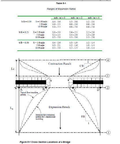
The Hydraulic Reference Manual has the following table (page 5-3) that shows the expansion ratio ranges based on contraction width, slope, and roughness values. In general the values range from 1:1 to 3:1, but to be on the conservative side I go with the higher values of 2:1 or 3:1. The only reason I would use a smaller value is if I had actually seen what the flow was doing during an actual flood event of similar magnitude of that I am modeling (which for a 100 year event is unlikely), I have calibration data, or results from a 2D/3D model.
If you can justify using a smaller value go for it and be sure to document how you justified it, otherwise I would go with the higher values from the table.
 cameronParticipant
In general I do a 1:1 contraction and a 2:1 or 3:1 expansion. These values follow the table in the user’s manual.
July 28, 2014 at 6:31 am in reply to: Imported and interpolated sections differing velocity results #8885cameronParticipantAre the bank stations and roughness values correct? When you interpolate, roughness values get interpolated also.
cameronParticipantThe MMC toolbox is similar to GeoRAS as it just uses tools that are already in ArcGIS and can be done without the toolbox, the toolbox just simplifies it.
As to where you can get the toolbox, the description of the videos contains the info (see description below):
This tool was designed and developed for the MMC Production Team by Gannett Fleming, Inc. For more details on the tool, contact Chris Krebs at [email protected]
cameronParticipantYes it is the precision when importing terrain data. It is a drop down menu so you should be able to change it some something else.
cameronParticipantYes it is the precision when importing terrain data. It is a drop down menu so you should be able to change it some something else.
cameronParticipantDoes the model run if you remove the culvert/lateral structure? Is the lateral structure correctly set up?
cameronParticipantWhat is your timestep for the unsteady model and what is the spacing of your cross-sections. I would suggest lowering the timestep or interpolating cross-sections to see if either one changes the results.
cameronParticipantI have had a similar issue before that I worked around by changing the Rounding (Precision) value.
-
AuthorPosts