Welcome to the RAS Solution › Forums › HEC-RAS Help › Influence of local cell mesh size and average time step on water depth
- This topic has 6 replies, 395 voices, and was last updated 6 years, 10 months ago by Zoran.
-
AuthorPosts
-
May 24, 2019 at 12:53 am #7306ZoranParticipant
Dear Modelers,
I try to build a 1D-2D unsteady flow model. I struggle to understand how it is possible that I get very different results if I perform the 3 following simulations:
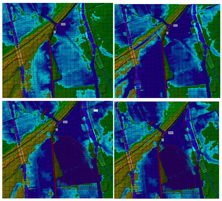
1. Benchmark experiment: a coarse mesh with cells of 10 m on the side; 5 sec simulation time step (upper-left figure)
2. Same as 1, but the time step is reduced to 1 sec (upper-right figure)
3. Same as 1, but the cells are 5 m on the side (lower-left figure)
4. Same as 1, but with both the time step reduced to 1 sec and the edge length reduced to 5 m (lower-right figure)The resulting water depth of the four simulations are very different as can be seen on the figure below.
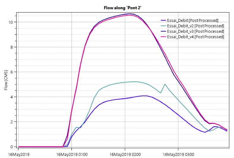
The next figure compares the flow across the section located before the hole across the embankment (simulating a bridge). The input hydrogram is linearly increasing – flat – linearly decreasing.
Il appears that the water level and flow discharge strongly increase when the time step is reduced and/or the cell size is locally reduced.
Reducing the time step can lead to a hydrogram with an increased peak flow, which can result in water propagating further. In my simulation it seems that there is a massive increase of water… Even more extreme is when I create a refinement zone at the upstream of the bridge. This has the effect to double the flow at the bridge and dramatically increase the water level and inundation extent.Is there an explanation for my results or is my simulation wrong ? I am wondering what time step and mesh size I should consider to get something coherent ? Is there something as a Courant number criteria for the 2D region ?
Best,
 May 24, 2019 at 1:06 am #12242AnonymousGuest
well whats your continuity error for each? please check your log file
May 24, 2019 at 4:10 pm #12243ZoranParticipantHi Luis Partida,
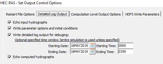
I don’t know how to access to continuity error. I cannot check the Computation log file after running my simulation (which is stabke) even if I activate the Detailed Log Output. It appears no .bco01 file is generated by RAS. This file should contain the Unsteady Flow Log output file. I use RAS version 5.0.6.
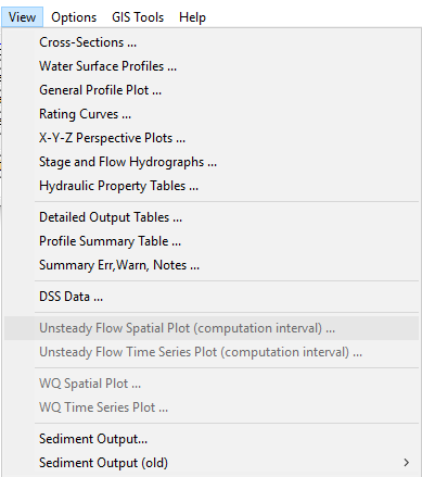
Also it is impossible to access to the Unsteady Flow Spatial Plot and Time Series Plot in the View menu.
What can I do in such situation?
Thanks
 May 24, 2019 at 8:43 pm #12244Scott MillerParticipant
In the plan window, pull down the options menu to ‘view computation log file’, but if there is not any .bco## file, this may not work.
The flow trials 3 and 4 look like they agree well. What you might do from there is to test sensitivity of grid cell size, while allowing the Courant condition to adjust the time step.
May 28, 2019 at 11:37 am #12245ZoranParticipantApparently opening the output log file from Option -> View computational log file is not working on my computer. There is a pop-up message that appears which indicates : “Note – There is not a log file to view”.
I finally managed to obtain the desired .bco## file by removing the old .bco## file and running the simulation again. After that, I could open the file with notepad directly from the file explorer. It was located in the folder where is save my plans.
According to my simulations, I would assume that the smaller the grid cell size is, the more accurate the model becomes, right ? This is true as long as the Courant number is close to 1 (which ensures that the ratio time step versus cell size is correct). So what I should do is to progressively decrease the grid cell size while adapting the time step with the Courant number, check if the solution converges, and once the solution is stable keep the associated mesh ?
Please correct me if I’m wrong.
Best
May 28, 2019 at 11:40 pm #12246Scott MillerParticipantThat sounds like a good approach.
You will be able to import the final mesh from an existing geometry to new geometries. That keeps the mesh consistent, in case nodes have to be moved manually.
May 29, 2019 at 11:32 am #12247ZoranParticipantGreat thank you for your advice!
-
AuthorPosts
- You must be logged in to reply to this topic.