Welcome to the RAS Solution › Forums › HEC-RAS Help › Hydraulic Structures inside of 2D Flow Areas (Where is HW an TW??)
- This topic has 8 replies, 990 voices, and was last updated 8 years, 3 months ago by robdir.
-
AuthorPosts
-
November 25, 2017 at 4:17 pm #6703robdirParticipant
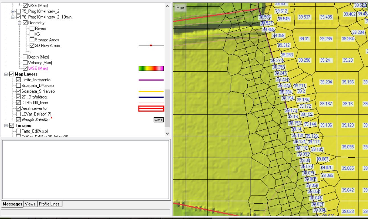
When I insert an Hydraulic Structure (like a levee) inside of 2D flow area, how are considered HW and TW in Stage and Plot Hydrograph?
If I draw the structure from up do down, which is the HW side? (see images attached).
https://drive.google.com/open?id=1HUYYf_Thh954CYpB9PbXs1_yG7W4sk11
https://drive.google.com/open?id=1ll0vzJjTU4Jm0PAKcl085fv9iFYVHddCNovember 26, 2017 at 12:39 am #11047AnonymousGuestI think your first image is correct. The hydraulic structure should be drawn left-to-right when you are looking at the profile of the headwater side.
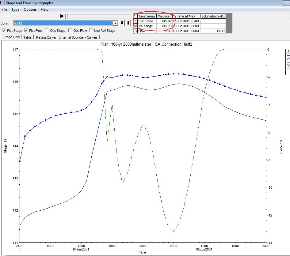
November 26, 2017 at 6:25 pm #11048AnonymousGuestI also think so. But I have some doubts about HW and TW values reported in stage and flow hydrograph of the connection. If you look at the graphic, there’s one (maximum) value assigned to HW andTW in the summary table . But I don’t know how Hec assigned it: is it a mean value of HW (and TW) between the cells “touched” by the connection? Is it the minimum value calculated for the cell with min elevation? Or is it anything else?
November 27, 2017 at 7:08 pm #11049Lonnie AParticipantEvery cell along the connector can have a different HW and TW. I believe what is reported in the hydrograph is the HW and TW from the lowest connected cell. If you want to know what the HW and TW is at a certain location you need to look at the results in Mapper. If you are just reading the max WSE and not plotting a hydrograph of the target cell within mapper be sure you set the render mode to horizontal so you get the elevation that the calculations are based on.
November 27, 2017 at 10:39 pm #11050robdirParticipantLonnie, what do you mean for “the lowest connected cell”? Is it the cell with min WSE along the structure? I checked it but it doesn’t correct. I tried to search for the min elevation’s cell, but it doesn’t correspond.
I think also that we must look at face values for the structure… it’s different from cell calues calculated in the cell centers.
What do you think about it?November 28, 2017 at 1:08 am #11051Lonnie AParticipantI think it is actually coming from the highest adjacent minimum cell elevation. I checked a recent model and the mapper WSE elevations match the results hydrograph stages for the two highest adjacent cells. The two cells located at the left end of the structure had the WSE that matched what was reported in the hydrograph output.
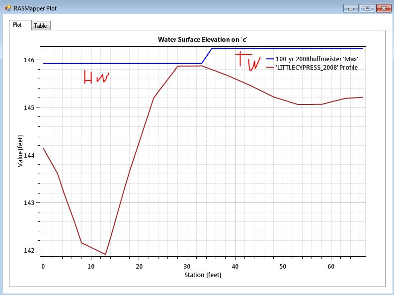
RAS mapper result
 November 28, 2017 at 7:51 pm #11052robdirParticipant
Thanks Lonnie, but I’m not sure…
I have a similar situation but my structure (hypotetical levee) wasn’t “surmonted” .
I tried to search for WSE elevations from cells along the connection (levee) but I didn’t find the matched values.
Where is located the profile that you posted?
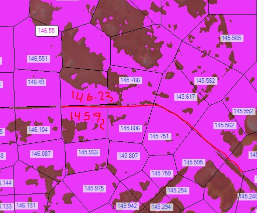
This is my case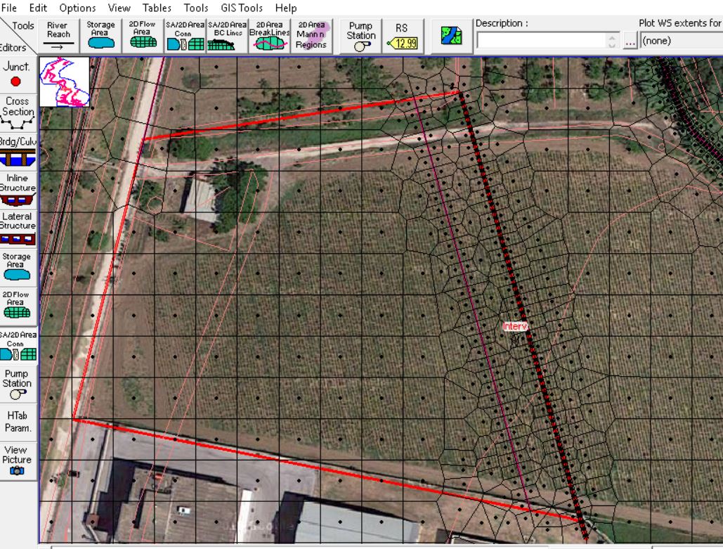
 November 29, 2017 at 9:23 pm #11053Lonnie AParticipant
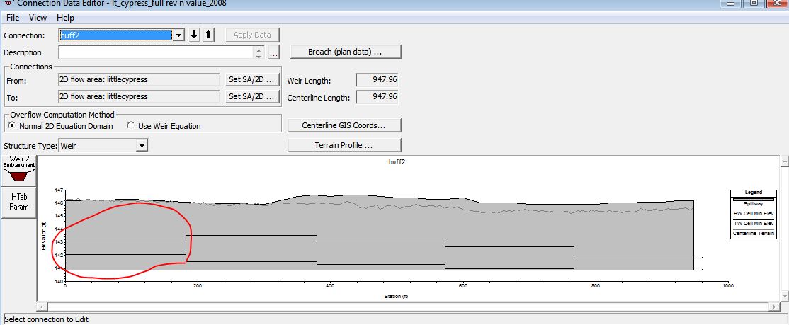
If cell centers don’t have a inundation under them they don’t report the WSE. I think this is because when you show depth it’ll vary within the cell based on the underlying terrain and since only reporting one value it uses the depth under the cell center, which if no inundation exist there, nothing gets reported. The attached shows the limits of the connector and I put penciled in the elevation (using horizontal render) to show the elevation matches the hydrograph.
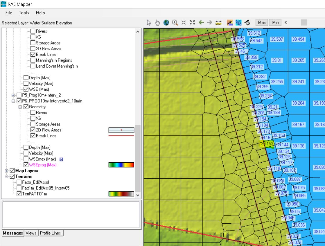
 November 29, 2017 at 10:13 pm #11054robdirParticipant
Sorry, I used similar colors for the WSE… In this image you can see that there is a WSE on the right side (referred to image) of the structrure
I highlighted (yellow colour) the WSE cell value that matched the max TW reported in Stage and Flow Hydrograph. I also checked the HW value: it was referred to corresponding cell on the left side of the structure (in this case it is the terrain elevation value = constant ).The cell highlighted was placed just at middle point along the “connection” line, so I can confirm that the max values reported in the StageFlowHydr are referred to the two cells (right and left side of the structure) corresponding to the middle point of the centerline connection (N.B.: the middle point was calculated consdering the Weirsta/Elev length- see Polyline Lengths in SA/2DAreaConn Centerline Table).
I’m searching for others simulations to verify this assumption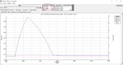
-
AuthorPosts
- You must be logged in to reply to this topic.