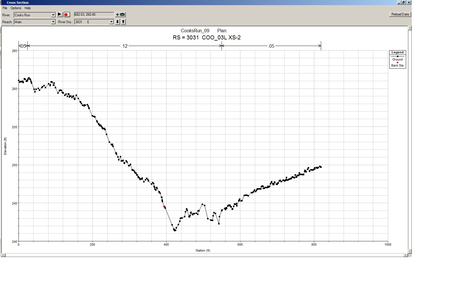
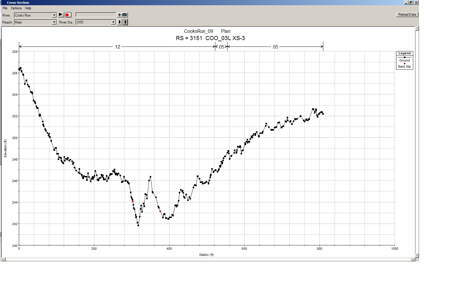
This topic is following up on the Comments in the “How to draw cross sections” blog entry.
I have placed my bridge bounding cross sections (Sections 2 and 3) parallel to my bridge. But I am having a hard time placing at the “toes” of the embankments and they are certainly not parallel to the flow.
I read through the skew bridge blog but I’m unclear on how to proceed.
Please note that it is a railroad crossing where I am expecting that my high flow (500-year) will be at least 3 feet below the low chord. So I am not currently worried about weir flow conditions.
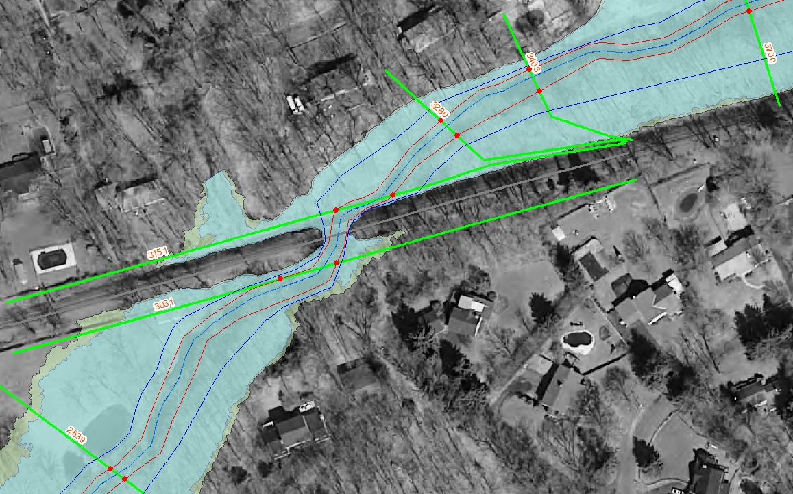
Here is a screen shot of the imagery and draft (1st run) 100-year & 500-year floodplains. Please note that flow direction is from top of screen (north) to bottom of screen (south).
It seems to me like my cross-sections are crossing the channel twice, greatly over-estimating the width of the channel (low-flow) portion. Will this be okay as-is? I plan to apply the bridge/culvert skew option and check the skew upstream / downstream XS same amount as deck. (Please note that I have not yet applied the “bathy” underwater survey data to the XSs shown here. This is straight from the LiDAR data. I will code in the underwater portion by hand after I am sure that the alignment is correct.)
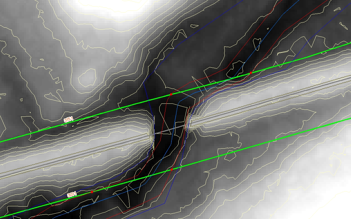
Here is another screen shot zoomed into the bridge opening with ground DEM and contours turned on.
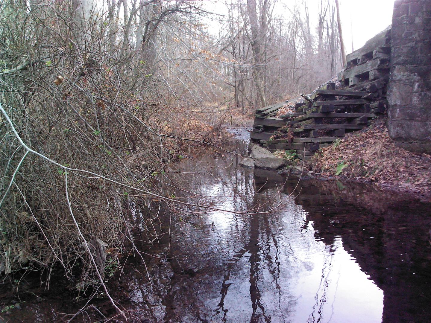
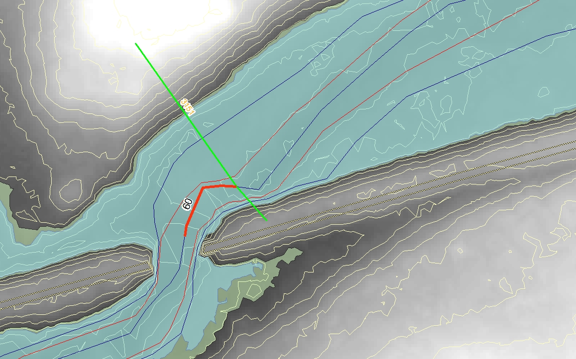
As a further complication, you may have noticed on the upstream side looking at the contours that there is a wall that sticks out. Here is the photo looking upstream.
The surveyors note that the distance from the upstream face to the upstream section (XS3) is 60 ft. The best I can tell is that my surveyors measured the upstream cross-section using a location and orientation similar to this figure. This avoids the stone wall but is certaintly not parallel to the railroad embankment.
