Welcome to the RAS Solution › Forums › HEC-RAS Help › Flow loss problem in a 1D/2D model
- This topic has 7 replies, 1,390 voices, and was last updated 7 years, 8 months ago by anthony.
-
AuthorPosts
-
June 8, 2018 at 4:00 pm #6924anthonyParticipant
Hello everyone,
Firstly, sorry for my english … I will try to be clear.
It’s a link google drive with screenshots : https://drive.google.com/open?id=190jz6DRsDp3KmH6kgqMuziCDda0v72Zg
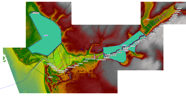
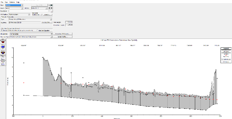
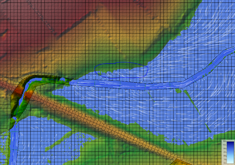
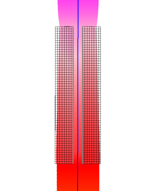
I realize a 1D/2D model on coastal stream, thus with maritime influence and I meet a problem for simulate a flow of 23 m3/s (Q100 years). My channel 1D is connected with my floodplains (2D area) by 6 lateral structures (3 on each side, cut near the bridge). I also have a 2d area in the estuary. I used rivergis to import my geometry. My geometry is presented below :
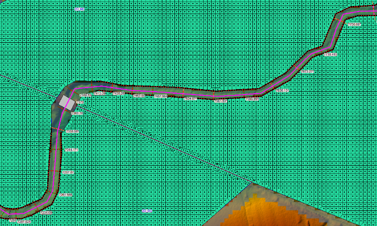
I have a loss of flow when the first lateral structures is reached. As you can see with the tracers of RAS MAPPER, the flow seems to converge and never to rejoin the stream in the 2D area right bank. The flow moves towards a higher ground. I put a breakline to take into account the dike, consequently the flow should be made by the bridge only. In the 2d area left bank, this problem is absent.
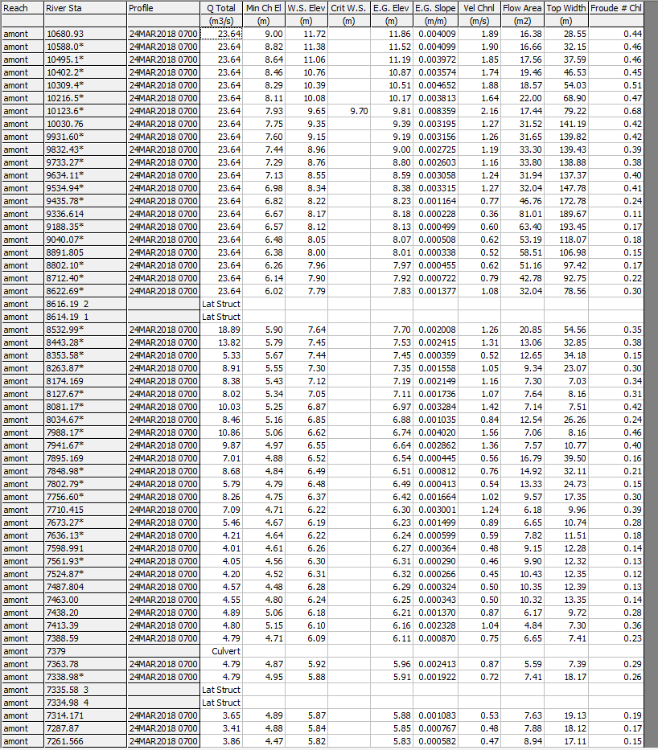
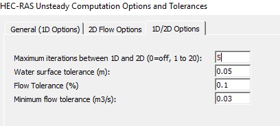
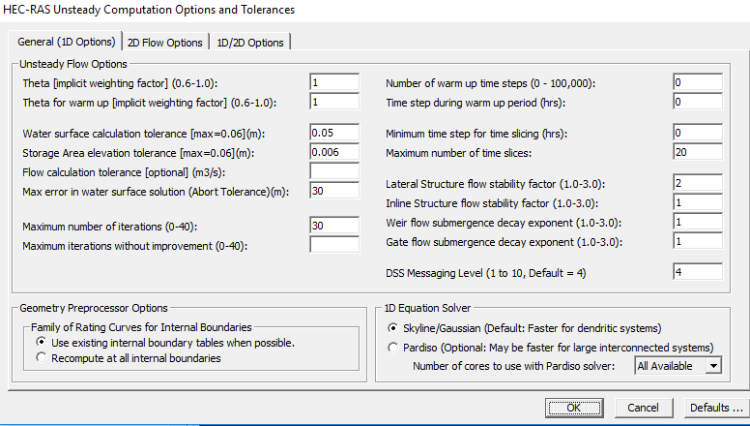
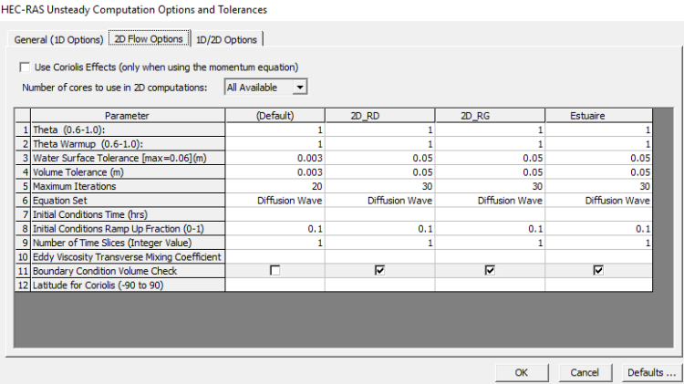
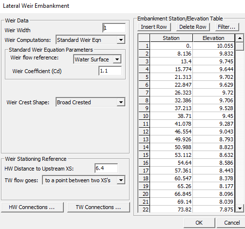
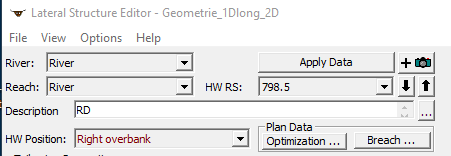
I enclose some screenshots of used parameters and results:
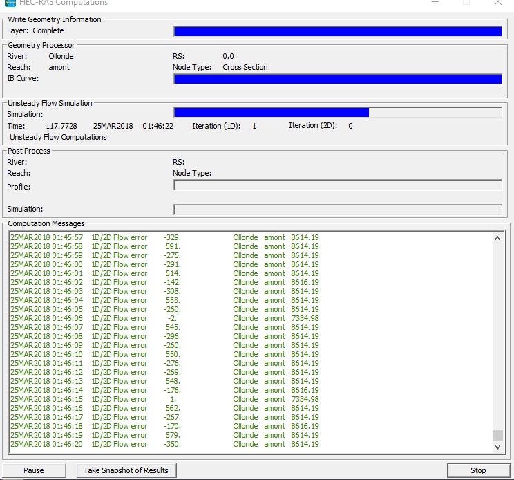
My mesh is 5 m x 5 m. My computation step was 10s, what is too high I think, I try currently with 1s, but my 1D/2D flow error is always in the same scale order. I use the version 5.0.3 of HecRAS.
I have many questions :
1) In my case, I use Normal 2D equation for my lateral structures. Is that good choice in my case ? I tried with the weir equation but the model was unstable.
2) My weir coefficient for my lateral structures is 1.1. I read on this forum that this maybe too high.
3) In the computation window, my 1D/2D flow errors is very high. My connection between 1D and 2D area is unstable ? Increasing the number of iterations between 1D and 2D will improve the results?
4) Do you have any others advices or suggestions please ?
Thank you very much for your time.
Anthony
June 11, 2018 at 5:30 pm #11435anthonyParticipantUp
I didn’t still solve my problem. I try currently to cut my laterals structures in several …
Do you have an idea please ?
Thank you,
Anthony
June 11, 2018 at 8:17 pm #11436Scott MillerParticipantHi Anthony.
I’ve dealt with some of the same things as you and think I can help a little. Take a look at this blog post regarding your first two questions: http://hecrasmodel.blogspot.com/2016/07/weir-equations-in-hec-ras.html
Regarding your third question take a look at this thread: http://hec-ras-help.1091112.n5.nabble.com/1D-2D-Flow-Exchange-amp-Minimum-Flow-Tolerance-td5485.html
Jarvus’ response to my question was helpful. Take a look at the mass-balance error in the computation log file under options. The 1D/2D flow errors you’re getting might not be so bad if your model is stable.
The lateral weir you show in your post is almost 1200 meters long. A lot of flow can pass across that boundary in a single time step. I think you could increase your minimum flow tolerance and 1D/2D iterations. (Your minimum flow tolerance seems incredibly low.) In the blog post linked above Chris Goodell wrote in reply to Toby:
As far as advice to reduce 1D/2D flow errors over lateral structures: Break up long lateral structures into multiple smaller ones. Be careful not to use too high of a weir coefficient. Do not have cells adjacent to the lateral structure that reside completely on the slope of the levee/berm/whatever you’re modeling with the lateral structure.As far as I can tell from the 1D velocities in your post, the 10-second time step ought to satisfy a Courant condition for the size of your cells. I’m assuming the velocities in the channel are the highest.
Scott
June 12, 2018 at 12:16 pm #11437anthonyParticipantThank you Scott. I had already read some of these articles.
I try currently to cut my laterals structures in several sections. Do we have to leave a “hole” between every section of lateral structure to have no problem of junction ?
I will also tried to increase my tolerance. Thank you of your advice(councils). I would make an experience feedback.
Anthony
June 12, 2018 at 8:17 pm #11438Scott MillerParticipantYou will need to leave enough of a gap between lateral structures so that no 2D cell has more than one lateral structure connected to it. You can add or move calculation points to accomplish this, or choose the ends of the lateral structure centerlines accordingly. I believe you can leave gaps as long as any high ground that does not become inundated along the center line.
I found that my model appeared to be losing flow between lateral structures. (About 2% error in the 1D reach. I could see particle traces in the 2D flow area accelerate to lateral structure gaps.) So I have reconstructed my lateral structures to end at the highest points along the flood plane. I believe this is like what Chris Goodell meant by “Do not have cells adjacent to the lateral structure that reside completely on the slope of the levee/berm/whatever you’re modeling with the lateral structure.” I would construct a short berm on the elevation model if there were otherwise no high ground.
For a point of reference, in my model the minimum flow tolerance has ranged from about 0.25 to 1.5 m^3/s for a reach about 1 km long on a stream that gets perhaps 12 m^3/s during an extreme event. I believe the minimum flow tolerance applies to each lateral structure.
June 13, 2018 at 4:06 pm #11439anthonyParticipantOk thank you Scott. I’m on the right way.
Another question please.
I am currently building a basic model to understand what HECRAS does with connections.
The HW position field is useless, no ? Or I don’t understand what hecras does with… I explain.
In my basic model, I deliberately drew large cross profiles in my 2D zones to see the influence of this field.
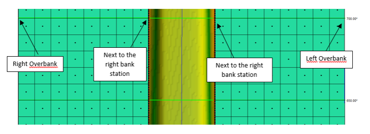
I tried “Right Overbank” and “Next to right bank station” (the same thing for the left side).The results are similar.
For me, I understand it that way :
However, from results, the connection still seems to be at the lateral structure. So what is the use of the HW position field please ?
How does it manage the superposition of 1D and 2D? I thought the “HW positions” field was used to define where the user wanted to overwrite 1D data by 2D as under MIKE (DHI) where a marker is used to define the location of the 1D/2D link.
Anthony
June 18, 2018 at 9:33 pm #11440Scott MillerParticipantThis is actually a new topic.
Here’s the way I read the headwater position in the manual:
Let’s say you have already built a 1D RAS model, and it extends across the floodplain. You can draw 2D flow areas on top of the 1D floodplains, without having to rebuild your 1D model. Use the “Next to
bank station” headwater position for this situation and draw the 2D area to match your bank lines or bank points (the edge of the main channel). If you are building a model that you know is going to be a 1D/2D model, you do not need to include the floodplains when you draw the 1D cross sections. In this case draw the 2D flow areas to match the ends of the cross sections, and use the “
overbank” headwater position. The 1D reach is always the headwater in RAS. The 2D flow area or storage area is the tailwater.
June 19, 2018 at 12:14 pm #11441anthonyParticipantThank you
Let’s say you have already built a 1D RAS model, and it extends across the floodplain. You can draw 2D flow areas on top of the 1D floodplains, without having to rebuild your 1D model. Use the “Next tobank station” headwater position for this situation and draw the 2D area to match your bank lines or bank points (the edge of the main channel).
Thank you for your answer. However, in the case 1 presented in the citation, the 1D calculation is done on the entire profile or not, even if we defined the 2D at the top of the bank?
-
AuthorPosts
- You must be logged in to reply to this topic.
