Welcome to the RAS Solution › Forums › HEC-RAS Help › Discontinuity in Results at 1D/2D Connection
- This topic has 9 replies, 1,232 voices, and was last updated 9 years ago by AJ.
-
AuthorPosts
-
February 7, 2017 at 2:06 am #6346AJParticipant
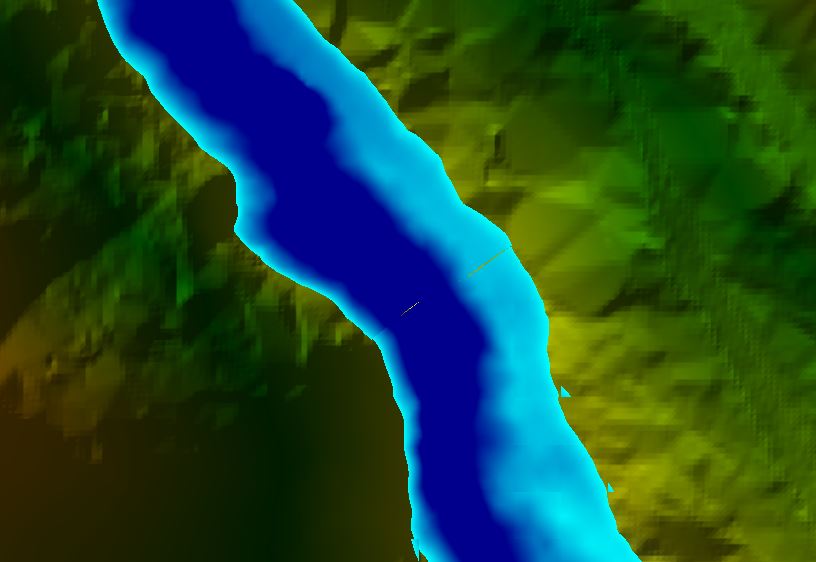
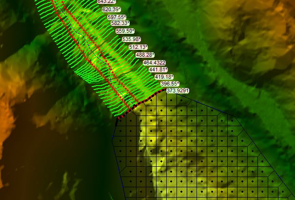
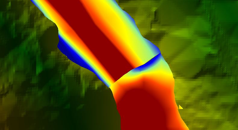
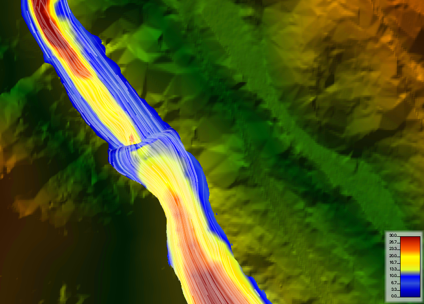
I have a model of a dam break. I was reviewing the results in RAS Mapper and noticed a discontinuity at the 1D/2D connection. I have attached a screenshot of the depth and velocity rasters at this location as well as geometry.
Can anyone provide any specific insight as to why this is occurring at the connection and any solutions to resolve the issue?
Depth:
Velocity:
Geometry:
February 7, 2017 at 3:30 am #10376AnonymousGuestThe rather uniform velocity in the 2D area looks odd. Does the terrain data contain the channel? If it doesn’t, you may need to add it.
A second possible issue: I’ve seen some small discontinuities at 1D/2D connections that I think are because the 1D/2D connection is passing the flow but is not passing the velocity/momentum like it should. It isn’t usually a big deal but if there are high velocities from the dam break, it could be part (or all) of the problem. From an HEC-RAS 2D class lecture, this was a known issue that was to be fixed for a future version. If this is the issue, try moving the boundary downstream where the velocities are slower. Or do the entire model either as 1D or as 2D without a connection at all.
February 8, 2017 at 3:05 am #10377AJParticipantJarvus, thanks for the comments. The terrain data does contain the channel. I agree the uniform velocity does look a little odd but right at the connection, the terrain really opens up (gets wide and flat) very quickly so it seems reasonable.
The aspect that is concerning is that at the connection the velocity goes from 27 fps (in the 1D) down to 6 fps (at the start of the 2D) for a short distance before going back up to to 20+ fps.
When you said in your comment that the 1D/2D connection is not passing the velocity/momentum like it should, is this only with respect to the graphics for the results or do you mean that the results are not reliable?
Because the terrain goes from a very steep and narrow canyon to a relatively wide and flat area fairly quickly, I don’t think I will be able to use 1D or 2D only and the connection is just upstream of the point where the terrain widens so I don’t think I can move it either.
February 8, 2017 at 3:45 am #10378TobyParticipant“This type of boundary condition should only be placed in areas where the flow and stage
are highly one‐dimensional in nature.” HEC-RAS 1d/2d manual pg. 63Maybe try and put the 1d/2d connection at station 464. Your flow is expanding as the slope changes and as the floodplain widens. Appears as if the flow may not be highly one-dimensional where you go from 1d to 2d. Another idea is to add more cells at the interface, but try to keep cells gradual as you change their size.
Does Manning’s from the 1d section match the 2d area?
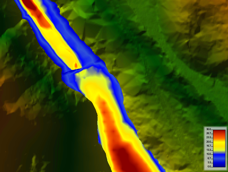
February 9, 2017 at 8:56 pm #10379AJParticipantToby, thanks for the suggestions. I moved the boundary upstream to a more narrow section of the canyon where the flow is highly one dimensional and added more cells at the interface. The manning’s n values are the same. The result is different but does not seem to have improved (see images below). I will try a 2D only model but was under the impression that 2D should not be used in areas that are highly 1D, especially areas that have steep terrain. The channel upstream is very narrow and has steep side slopes.
Also, the particle tracing on the velocity layer seems to indicate a break at the boundary between 1D and 2D (see image below). Any thoughts on this?
February 9, 2017 at 11:22 pm #10380AnonymousGuestRE: ” I will try a 2D only model but was under the impression that 2D should not be used in areas that are highly 1D, especially areas that have steep terrain”
No. I do not agree with this, at least as a general rule. The 2D solution uses finite volume and it generally does better with high velocities than the 1D that uses an older, finite difference approach.
2D does fine modeling flow that is highly 1D as long as the 2D mesh is appropriate. For instance, it is generally best to have the cells small enough so that the channel is several cells wide.
The issue with modeling a steep, high velocity flow with 2D is the computation time. The cells are generally going to be smaller than the equivalent 1D cross section spacing. Small cells with high velocities require a small time step. This is especially true if the 2D full momentum equation is used (which, for a dam break, it generally should be). So you might have a situation where the 1D could use a 5 or 10 second time step, but modeling the same region with 2D might require a 1 second time step. Add in the fact that 2D takes more computational power and run times get a lot longer.
But if run times are not an issue (or an issue you can live with) and you have good terrain for the whole model, I would think you should be able to do it all as 2D and not have the discontinuity.
For the velocity issue at the connection, I think it is more than just an output issue, but I don’t really know if it has that big of an effect on the overall accuracy or not. Dam break studies tend to have a lot of unknowns so the slight drop in velocity for a short distance may not really matter in the bigger picture. I didn’t go look, but the RAS Hydraulic Reference manual might have a discussion about this.
Also, you could convert the entire model to 2D and run it and then compare the answers that the 1D and the 2D get in the steep, narrow section.
February 10, 2017 at 4:55 am #10381AJParticipantjarvus, thanks for the input.
I ran it as 2D only, and the velocity was much lower and the depth was slightly lower. the flow was also lower. however, i could not get the 2D only model to run with cell sizes small enough so that there were several cells covering the width of the channel. best i could do was a few cells wide for the channel (full momentum, time step of 2 sec, cell spacing 25×25). the model ran well though with minimal errors. I tried going with smaller cell sizes (down to 5×5 to cover the channel) and decreasing the time step but the errors were to high to be acceptable (> 1 ft).
The question now is how do I know which one is right? Do I need to do a sensitivity analysis for both models on several of the parameters to know for sure? At the down stream area of concern (where there are houses), the results are pretty similar, the difference in velocity and depth are less than 1 fps and 0.7 ft, respectively. So are both results acceptable?
On page 6-4 of the 2D Modeling User’s Manual, it is suggested that 1D may be more accurate for steep streams that are highly gravity driven with small overbank areas (this describes the upstream portion of the terrain in my model). So is the only way to determine which method to use (1D or 2D) to do both?
February 10, 2017 at 7:28 am #10382cameronParticipantWhen you tried the 1D/2D model, did you have the 1D/2D iterator set to 20 (or any value)?
In your case, I would probably go to 2D only route with a 25 ft spacing, but do a sensitivity on the the time step. The rule of thumb most people use is to follow the Courant criteria which in your case would be less than 1 sec and gradual increase it to see how the results change. If you go too low with a time step HEC-RAS may give velocities that are too small and higher depths (this generally only occurs in areas with high velocities).
When you say velocity and depths are 1 fps and 0.7 ft different, different to what (30 fps, 10 ft of depth)? How different is the time to peak, or flood wave arrival time, or the deflood time, or peak discharge?
One thing you may try is to adjust the cell faces so that they are perpendicular to the direction of flow.
How important is it that you model the steep channel area? you have a breach hydrograph and could just place it near the area where it begins to expand.
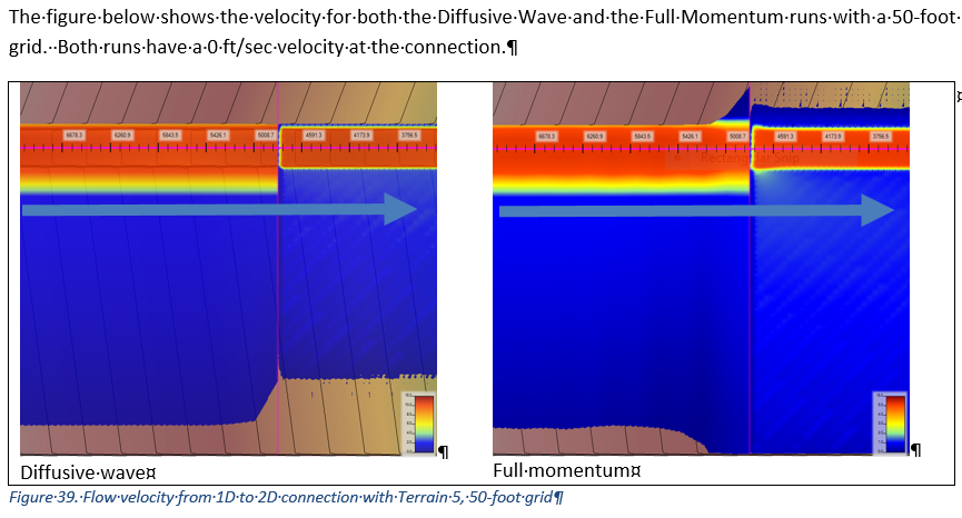
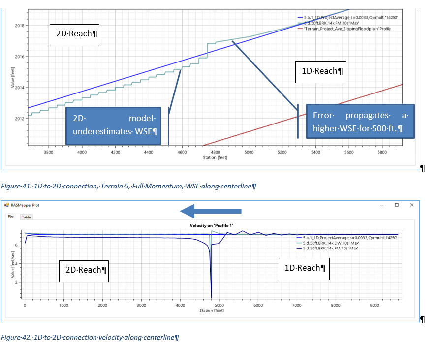
February 13, 2017 at 10:07 pm #10384Ian SharpParticipantI have had the exact same problem in a number of models. There appears to be a mismatch in the velocity at the 1d/2d boundary. If you plot the velocity along the flow centerline you might see an abrupt spike and the velocity will reach zero at the connection.
It occurs in both 2D to 1D and 1D to 2D. And it occurs if I use Diffusive Wave or Full Momentum, although DW does better in handling this. I have tested this further to analyze grid size, orientation, stream slope, and other issues. Ultimately it seems to me that this is an insurmountable boundary constraint type issue at this time. Maybe it will be resolved in later releases?
February 14, 2017 at 2:15 am #10383AnonymousGuestI’m a little hesitant to say too much without knowing anything about your model. But in the context of a dam break, I wouldn’t usually be too concerned about a difference of 1 fps or 0.7 feet. Dam breaks have a lot of unknowns: how full is the reservoir (piping or overtopping breach?), how much inflow is there during the breach, how quick does the breach happen. In addition, the dam break does not take into account all the mud and debris that is usually picked up. But it depends a little bit on what the study is going to be used for and whoever reviews the model might also think differently.
I read the page 6-4 of the User manual. I took it to be that the 1D model might be as good as or possibly better than 2D. I didn’t take it to mean 2D shouldn’t be used at all in that scenario.
1D can have stability problems with steep dam breaks. But if the model is stable, 1D can certainly give good results. With a fine enough mesh, I would think 2D would also give good results. But if the channel has shallow overbanks and the flow is only a few cells wide, the 2D could well be less accurate.
-
AuthorPosts
- You must be logged in to reply to this topic.
