Welcome to the RAS Solution Forums HEC-RAS Help culvert-expansion and contraction reach length

Viewing 9 posts - 1 through 9 (of 9 total)
  • Author
    Posts
  • #5560
    Anonymous
    Guest

    I have just been reading example 3 [single culvert(Multiple identical barrel)] in hecras manual. It is mentioned that we should be careful about culvert contraction and expansion length and suggested to use some equations(Hec ras reference manual- appendix B page 8) which obtained from real examples. I was wondering if these equations are being used by modelers to design culverts? If not how modeler determine expansion and contraction length?
    Cheers.
    Mike

    #8893
    jadams
    Participant

    Easy rule of thumb is 1:1 ratio for expansion contraction. This is why i ensure field survey information at the culvert mouth and atleast the culvert width from each end.

    #8894
    Anonymous
    Guest

    Joe Thanks for response.
    I found some information in hecras user manual (pages 6-25 to 30). It suggests that use 1:1 ratio for contraction and use (Table 6-1range of expansion ratio- page 6-28 of user manual).
    Cheers

    #8895
    cameron
    Participant

    In general I do a 1:1 contraction and a 2:1 or 3:1 expansion. These values follow the table in the user’s manual.

    #8896
    Anonymous
    Guest

    Hi cameron,
    you mean if the length of my culvert is 200 m( obstruction length is 100 m), the expansion reach length should be 100 to 300 m?! Isn’t it too much?
    cheers.

    #8897
    cameron
    Participant

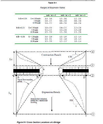
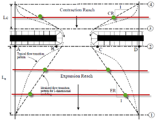
    The Hydraulic Reference Manual has the following table (page 5-3) that shows the expansion ratio ranges based on contraction width, slope, and roughness values. In general the values range from 1:1 to 3:1, but to be on the conservative side I go with the higher values of 2:1 or 3:1. The only reason I would use a smaller value is if I had actually seen what the flow was doing during an actual flood event of similar magnitude of that I am modeling (which for a 100 year event is unlikely), I have calibration data, or results from a 2D/3D model.

    If you can justify using a smaller value go for it and be sure to document how you justified it, otherwise I would go with the higher values from the table.

    #8898
    Anonymous
    Guest

    Thanks Cameron for your complete answer.
    Is n’t it a good idea to use smaller value (1:1) and define ineffective flow area based on 1:2 or 1:3 in the other cross sections?
    In this way, upstream and downstream cross sections ( xs 4 and 1) is not too far from culvert and we can diminish the effects of expansion,contraction.
    Cheers.
    Mike

    #8899
    cameron
    Participant

    Cross-sections 1 and 4 are supposed to be at the beginning/end of contraction/expansion and cross-sections 1 to 4 represent the minimum number of cross-sections required to model a structure. It is very common to have more cross-sections than 4, I do it all the time. The table/figure is just telling you that if you have cross-sections between 1 and 2 or 3 and 4 (red lines), you need to apply ineffective flow areas to them based on the table (green dots).

    #8900
    Anonymous
    Guest

    Thanks.

Viewing 9 posts - 1 through 9 (of 9 total)
  • You must be logged in to reply to this topic.