Welcome to the RAS Solution › Forums › HEC-RAS Help › Connection 1D-2D with terrain (NO LEVEE)
- This topic has 31 replies, 2,353 voices, and was last updated 7 years, 2 months ago by SaraA.
-
AuthorPosts
-
November 28, 2018 at 1:47 pm #7135SaraAParticipant
Hello,
I am trying to connect a 1D river reach to a 2D area where there is NO a levee. It is DIRECTLY the terrain connecting the 1D and 2D.
Following the 2D manual, firstly, I tried to connect 1D and 2D using a LATERAL STRUCTURE with a georeferenced centerline. THIS CENTERLINE SNAPS PERFECTLY WITH THE END OF THE 1D CROSS SECTIONS AND THE 2D MESH. I did it in ArcGIS.
However, I have issues copying the terrain elevation into the Weir/embackment.
The problem is that the terrain is located between the upstream (HW) where I located the weir, and the cross section just downstream of that one. I COULD NOT DO IN THIS WAY.I tried directly with a BREAKLINE using the same georeferenced line and selecting it as connection (Convert this Break Line into a new internal SA/2D area connection). I do have an issue when I FILTER THE LINE BECUASE IT HAS MORE THAN 500 POINTS, when I do that, now the weir has lower elevations than the cell to which it is connected.
I think does not matter if I snap the breakline with the end of the cross section in ArcGIS, if after I filter the line with less than 500 points… I loose this precision and I return to the same problem.How can I solve this problem?
Thank you in advance,
Sara
November 28, 2018 at 5:12 pm #11925AnonymousGuestYour second method is the best way to do it.
Yes you lose precision by filtering. The 500 point limit i was told was no l onger a thing, but i guess it still is… heres a way around it
Create the breakline and convert it as you said… but first set the min and max spacing to 2 to 3 times higher than your computational mesh and enforce it then convert it.
Now create another breakline in the 2D area immediately downstream of the structure. Right click the break line and set the minimum andmaximum spacing to 2 to 3 times above the computational mesh size you are going for and enforce it. This allows the terrain that is read per cell to match the spacing of the mesh.
This can be irritating but if you think about it, cross sections have a limit of 500 points also. So technically you can find the correct spacing to match the accuracy of the 1D cross section
November 28, 2018 at 7:08 pm #11926SaraAParticipant– deleted –
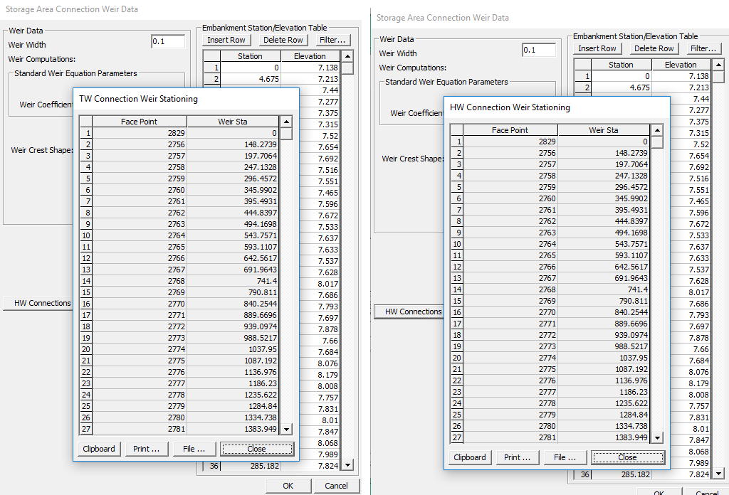
November 28, 2018 at 9:57 pm #11927AnonymousGuestThe users manual is complete garbage and ive mentioned it before. The downstream breakline allows the structure to read US and DS (HW and TW) elevations at very similar values.
I see your situation now a little better…3000m long weir is very very long. This is what i suggest then, connect the 1D reach to a 1D storage area which its only purpose is to let flow right into the 2D area. Connect your 2D area to the 1D storage area
If i am still missing the point. please add a few pictures and i can try and be of better help
November 28, 2018 at 10:41 pm #11928SaraAParticipantHi Luis,
I am trying to upload pictures…but I could not fin the bottom in this forum! I also tried copy and paste…but not works….how can I do it?
Regards,
Sara
November 28, 2018 at 11:50 pm #11955AnonymousGuestHi Sara,
There used to be a blog/post on instructions on how to upload images to this blog…i cant find it at all right now. Hopefully someone else looks at this and uploads the link
November 29, 2018 at 4:19 am #11929cameronParticipantJust break it up into multiple 2D connections
November 29, 2018 at 12:58 pm #11930SaraAParticipantHi Luis and Cameron,
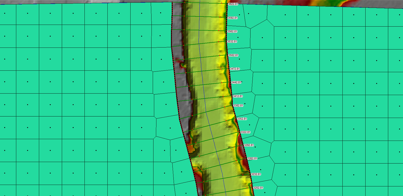
This how looks my conexions in the upstream part of my river
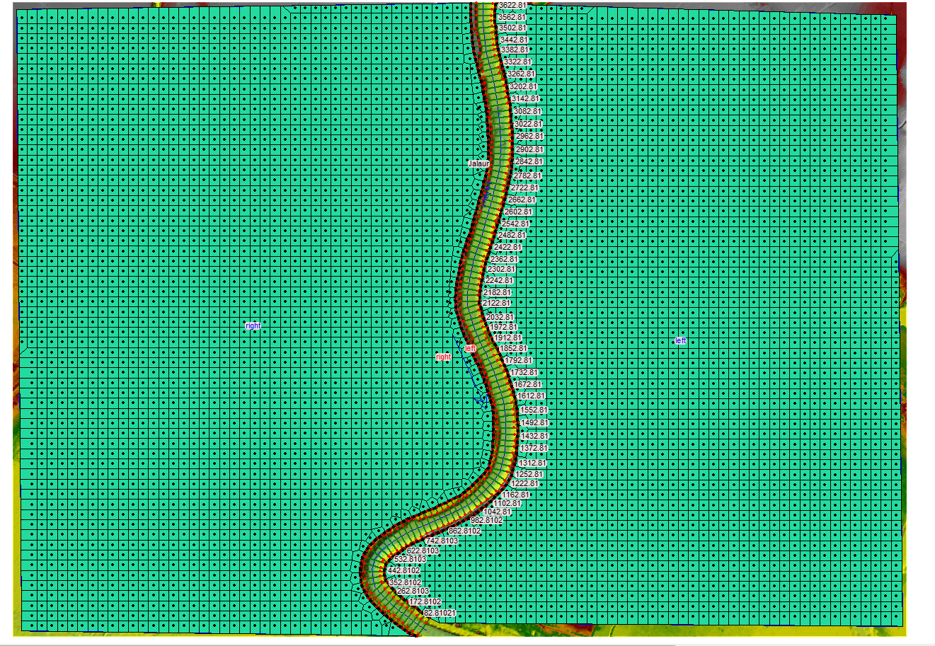
and this how looks the complete model…the breakline is continuous as I said (3km lenght) and I could solve the issues of the cell/weir elevation discrepancies making only three slight modifications of mm in the weir/elevation table.
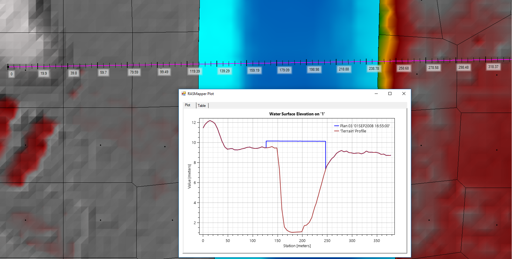
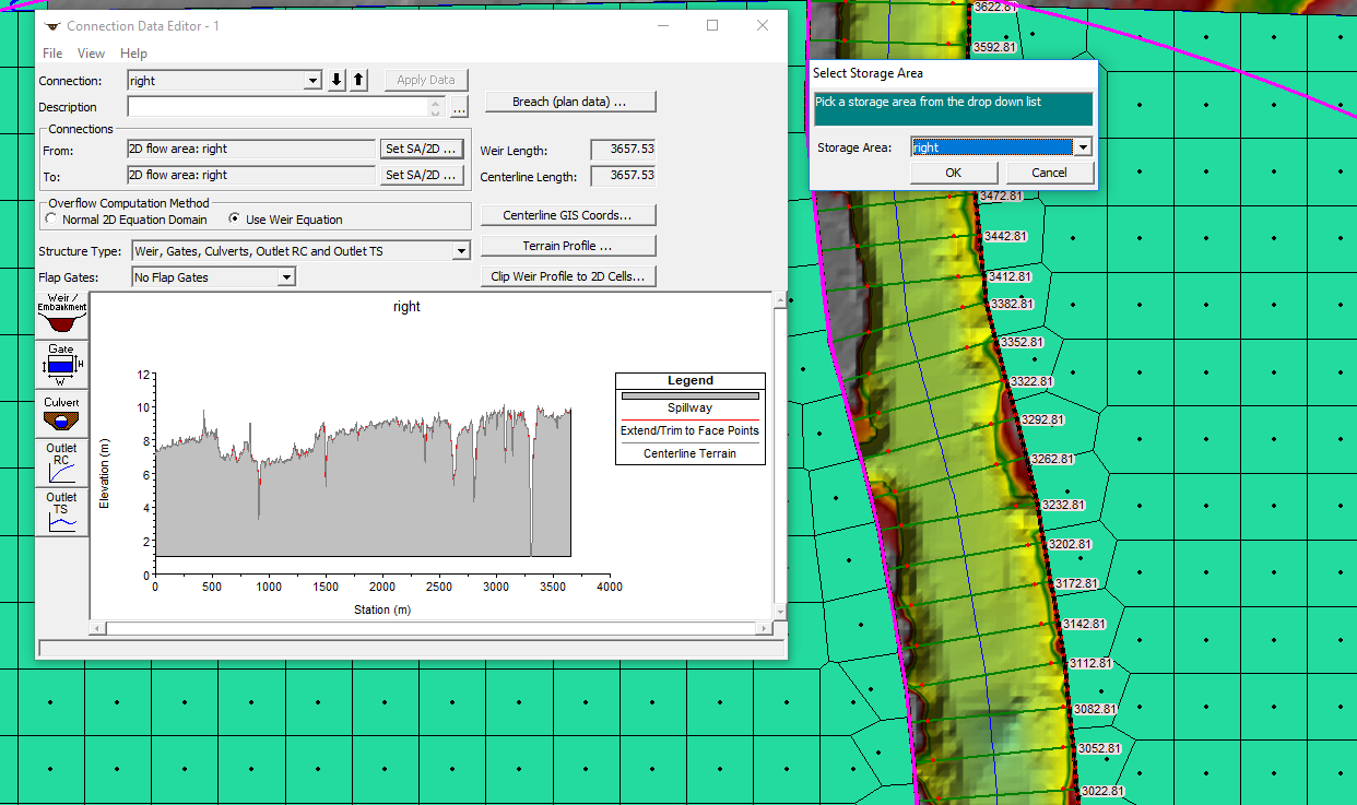
and finally, this is how looks the conexion of my breakline with the 2D area on the right.
When I ran the model, the results I got are very weird, with water level elevations of 150 m in the most upstream, like there is not a connection between the 1D and 2D area…
Could some of you give me an insight in which is there my error?
Should I put a boundary condition in the 2D area to allow the water flows out of the area (for example a normal depth)?
At the moment, I only have two boundary conditions upstream (hydrogram for 66 hours) and downstream of the river (critical depth, normal depth = 0.1)Thank you,
Sara
November 29, 2018 at 5:07 pm #11931AnonymousGuestI see
Yes always give your model a way for water to get out, look in RAS mapper to see if there is head build up at the edges of the model; if not then a boundary condition is not needed.
It is recommended that the weir coefficient be between 0.2-0.5….if the weir becomes submerged
This will change model results and stability
November 29, 2018 at 7:00 pm #11932SaraAParticipantHi Luis,
Should I consider more things related to the connexion than the last image I sent where the breakline is connected to the 2D area? Should it not be connected to the 1D? How can I do that? (The only way I saw it is creating a lateral structure, not a breakline… though the interfaces of both look similar)
As you can see in the image, the water does not flow from the 1D to the 2D and I can not find why this happens or why they are not correctly connected.
Thank you,
November 29, 2018 at 8:20 pm #11933Scott MillerParticipantWhat happens when you use the centerline coordinates to make a lateral structure to connect 1D and 2D in the model, instead of a break line? That is the purpose of a lateral structure. The lateral structure is also used to connect 1D to a storage area. The 1D/2D connection should be automatic when using centerline coordinates. To my understanding, a breakline is used to lock in elevations along an alignment within the 2D area, such as along a berm or roadway.
Give lateral structures a try with a copy of the geometry. Try shortening the structure length and put the ends of the structure at high points along the profile. Leave enough space between the ends of different structures, so that they do not occupy the same mesh cell.
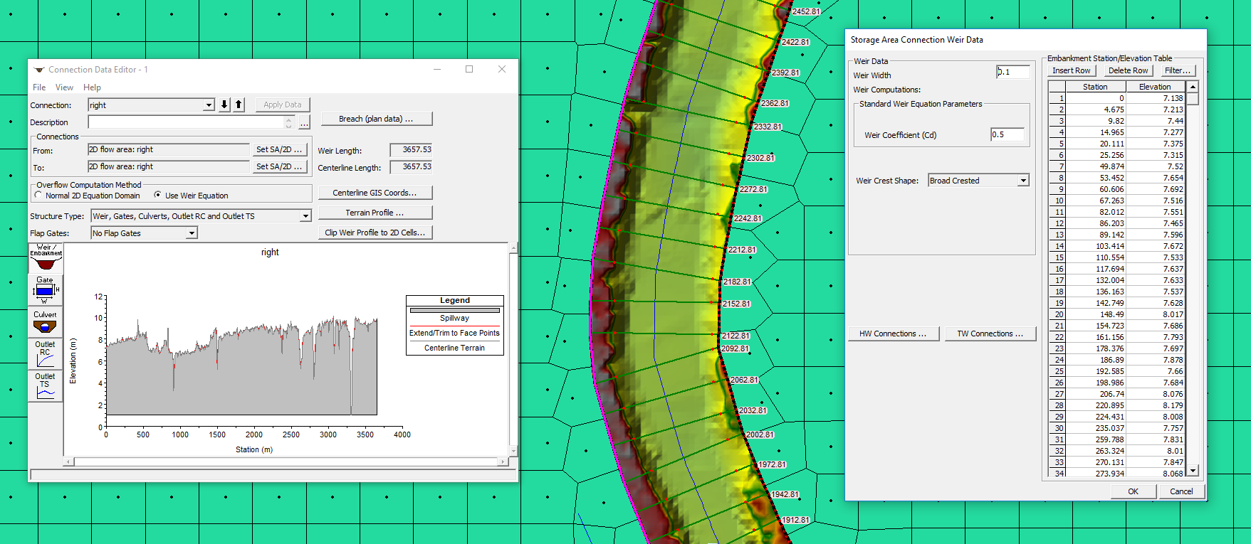
November 29, 2018 at 9:22 pm #11934AnonymousGuestHi Sara i see the problem now. Please look at the image you send showing the lateral structure data.
Look where it says “Connections”
Its not connected to the 1D cross sections. “From” and “to” need to be changed and show one being the 2d area and one being the 1d geometry
This will fix your model entirely. Make sure to change your weir coefficient as well as previously mentioned anywhere between 0.2 to 0.5
November 30, 2018 at 11:38 am #11935SaraAParticipantHi Luis and Scott,
Thank you for your help!!
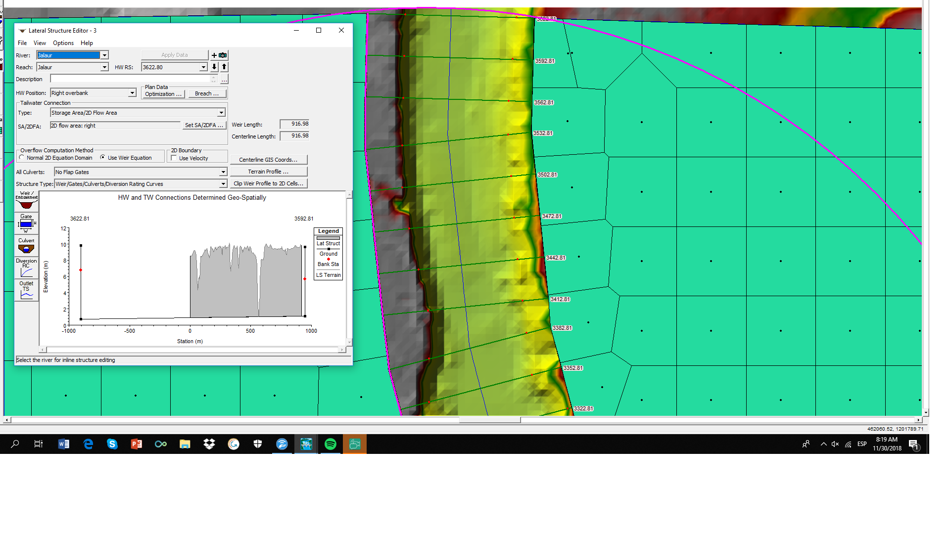
I tried with a lateral structure the connexion between 1D and 2D without success. I imported a georeferenced line from GIS with the coordinates. After, I copied the Terrain Profile under this georeferenced line and copy it into the weir/elevation data. As you can see in the image, the plot of the terrain is putting all the terrain for the completed line concentrated between the HW cross-section of my lateral structure (3622.81) and the next one (3592.81). The plot of the lateral structure does not show all the cross-sections to which my lateral structure cross.
Do you know how may I solve this problem?
Also when I tried with the breakline in which the terrain looks well…how can I connect it with the 1D? In the interface of the breakline editor, the only connexion available that I can see is to the 2D area. I checked the HW and the TW connections Luis, and you are right, both are the same…but how can I connect to the 1D?
Thank you for all your help,
Sara
November 30, 2018 at 6:21 pm #11936AnonymousGuestYour first image is correct…forgive me the breakline option i suggested is only for 2D only
Use the lateral structure editor on the left of geometry editor as your first image suggested. your stationing and lengths are wrong. To help solve your problem for understanding purposes…delete all teh 2D areas and try connecting a small weir to only 4 cross sections. This will help your understanding of stationing and how the structure connects to the HW TW. HEC-RAS nomenclature is always standing upstream looking downstream, left to right.
November 30, 2018 at 8:54 pm #11937Scott MillerParticipantThe stationing on lateral structures is confounding at first. River stationing usually increases from downstream to upstream. Lateral structure stationing increases in the other direction, from upstream to downstream. They do not match numbers, except that when the lateral structure is named you give it a river station number.
There will be a 1D cross section upstream from the start of the lateral structure. The lateral structure name (number) must be less than the cross section number, even if it is only by a millimeter. That arranges the cross sections and structures in the correct order. It is not necessarily the actual distance, so don’t worry too much about it. The lateral structure name can be changed (to a different number), if needed, to put it in the correct order.
Do this for the upstream distance to cross section: From the lateral structure editor, click on the weir/embankment button. Enter and estimate of the distance to the upstream cross section. Close to the lateral structure editor. The cross sections and the embankment elevations should show on the ls profile. Click on the upstream cross section on the profile. The coordinates of the point you click are displayed. Read the negative lateral station ordinate for the up stream cross section, go back to the weir/embankment editor, and enter this accurate distance [as a positive number] to the upstream cross section.
Besides doing this, there should be automatic mapping of the headwater 1D cross sections and the tailwater 2D mesh cells to the lateral structure stationing. [Be sure the tailwater connection is the 2D area.]
Other things to watch out for: it can be easy to forget to set the lateral structure position to the left or right bank, but it looks obviously wrong in the geometry plan plot. And if you interpolate cross sections near the upstream cross section, it may be necessary to re-do the upstream distance and lateral structure name. Lastly, the lateral structure length must be within 0.5% of the river length it is adjacent to. Big meanders can mess with the length.
Try out the lateral structure and let us know how it goes.
-
AuthorPosts
- You must be logged in to reply to this topic.
