Welcome to the RAS Solution › Forums › HEC-RAS Help › Comparison of the flow over a weir in the geometry editor and RasMapper
- This topic has 1 reply, 48 voices, and was last updated 5 years, 5 months ago by Zoran.
-
AuthorPosts
-
October 5, 2020 at 5:57 pm #7774ZoranParticipant
Dear all,
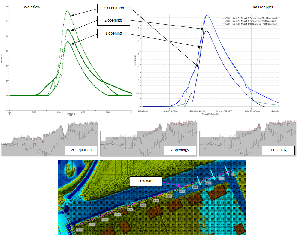
In order to prevent my terrain from being flooded, I made a ditch to collect and evacuate the water coming from the north. Digging the land resulted in more water being drained than initially, thus worsening the flooding on the terrains south of my plot.
To avoid this, I added a low wall with one or two overflows to the north of my land to limit water inflows. My goal is that there is as much water arriving on my terrain after the creation of the ditch, the wall and the overflow(s) than in the initial situation.
To know the quantity of water arriving in the initial situation, I created an internal SA/2D Area Connection and applied the altimetry of the ground as weir elevation. To best simulate natural terrain, I chose Normal 2D Equation Domain.
Then I calculated the width of my overflow(s) allowing the right flow to pass for different reference floods. Since my theoretical results and those of the simulations do not agree, I decided to determine the width of my overflows by iteration (trial-error).
I have two possibilities to analyse my results:
– study the flow rates that pass over my low wall in the geometry editor
– study the flow rates that pass over my low wall through a profile line positioned at the same place as my weir in the RasMapperThe problem is, these results are different and I wonder which ones are correct ?
It appears that the results are completely reversed: 2D Eq leads to the maximum flow rates for the weir flow, while the flow is the lowest in the RasMapper… Why this difference?
Personally, it seems to me that the flow rates obtained in the geometry editor are more correct, but I would have liked to have an external opinion on this point. Generally speaking, I wonder if I can trust the graphics of the RasMapper?
The following figure shows the flow rates over the low wall (left: weir flow, right: RasMapper) for 3 different simulations (no wall, wall with 1 overflow, wall with 2 overflows), the shape of my overflows and an illustration of my results.
Thanks for your feedback,
Best,
 October 7, 2020 at 12:18 pm #12961ZoranParticipant
I think I have found an answer to my question.
For this I created a retention basin with a single overflow in which I injected a constant flow of 2 m3 / s. I then compared the graphics obtained in the geometry editor and in the RasMapper.
It appears that the graphs given by the geometry editor are correct: following the filling of the basin, we observe a constant output flow rate of 2 m3 / s.
Regarding the graphics given by the RasMapper, it appears that the positioning of the profile line influences the result! Indeed, when the latter is parallel to the weir but shifted by one cell, the results are correct (cf. PL top and bottom in the figure). On the other hand, when superimposed on the weir, the flow rates are too high (sometimes far too high).
Maybe this is explained by the fact that the RasMapper artificially adds the back and forth movement of water above the structure (oscillations)?
In conclusion :
– the results of the geometry editor are correct
– the results of the RasMapper are correct as long as the profile line is not positioned directly on the structure (the profile line must not be magnetized to the structure)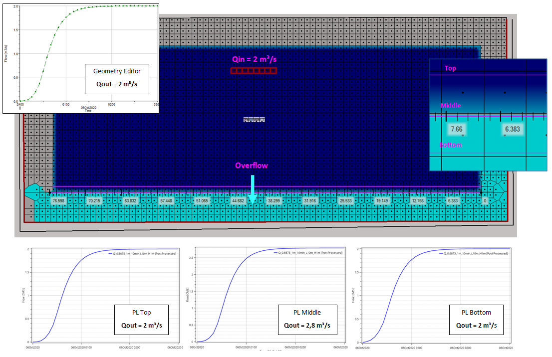
-
AuthorPosts
- You must be logged in to reply to this topic.