Welcome to the RAS Solution › Forums › HEC-RAS Help › Bridge modelling in 2D
- This topic has 8 replies, 1,941 voices, and was last updated 7 years, 4 months ago by step.
-
AuthorPosts
-
October 24, 2018 at 12:47 pm #7098stepParticipant
Hi
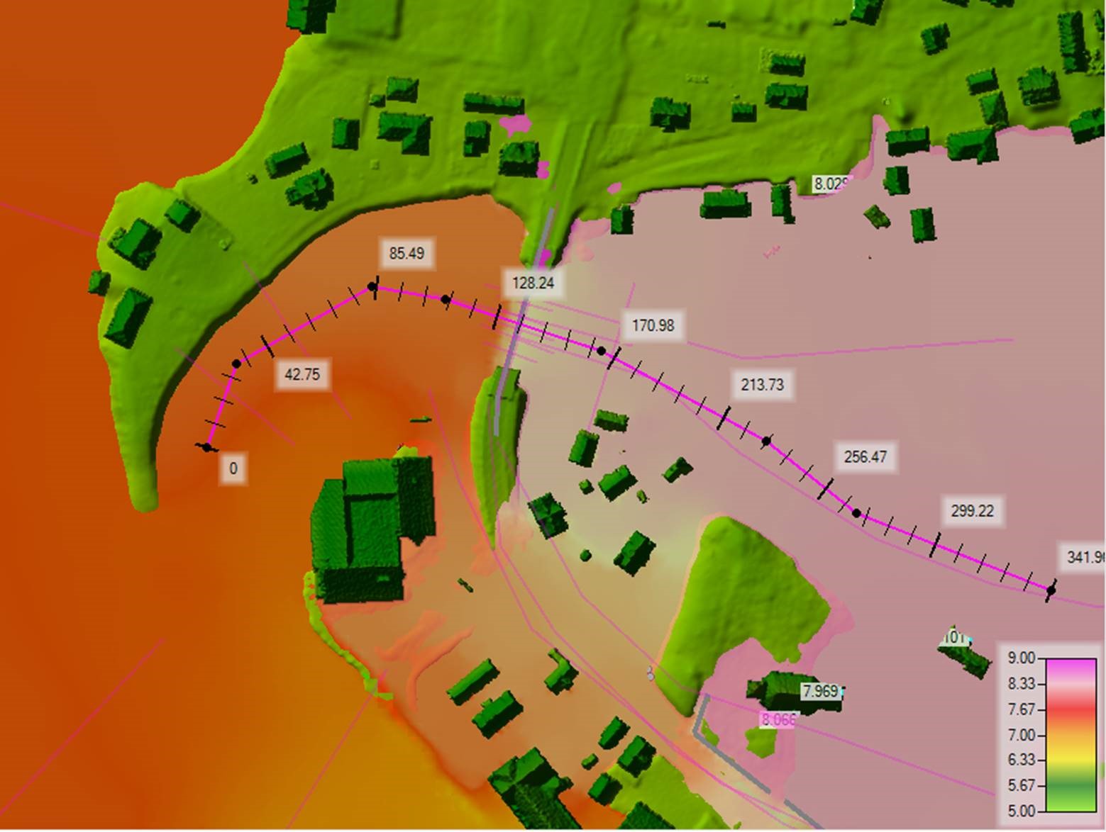
I am trying to model a scenario with a bridge in 2D where the water level reaches the bottom of the deck but there is no overflow. The bridge deck is higher than the terrain on the sides where some flow is expected.
-bridge abutments are modelled as a change in the terrain.
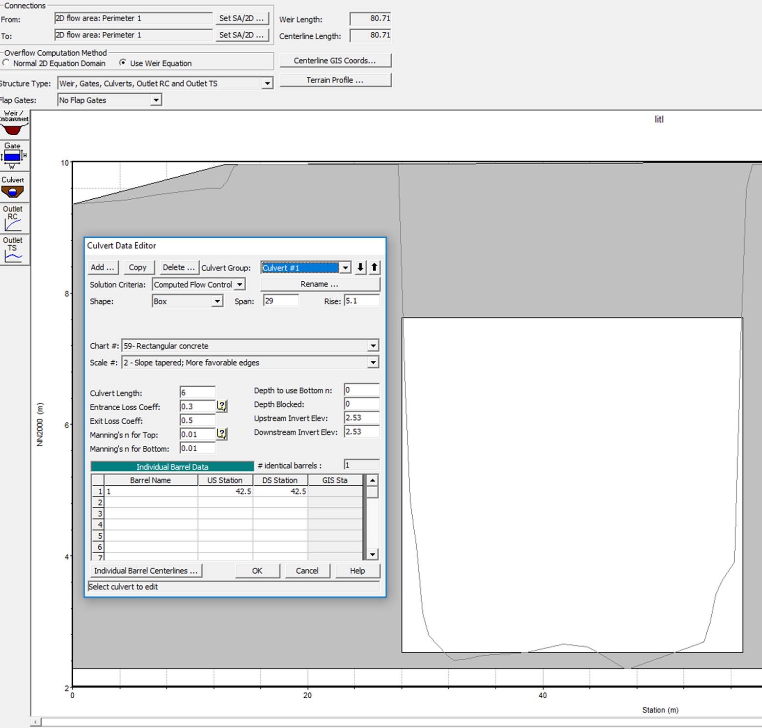
– i use culvert to model my bridge. The loss coefficients are set to 0.3 and 0.5 as I found in literature that these values are typical for a bridge opening.
– I have calibration Points from a rather large flood event, during which the water Level was barely touching the bottom of the deck.My problems are:
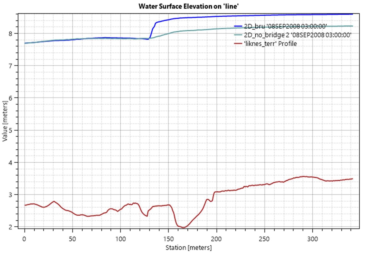
-when I model With the bridge geometry just as change in terrain I get a results close to calibration Points. (+10cm higher )
-when I model the bridge as a culvert I get a large rise in the WSE upstream the bridge and the results are about 50cm higher than the calibration Points.
-when I model with the use of a culvert, I get slight instabilities
-I have to use this model for a much larger flood therefore; I expect pressure flow to occur in the bridge openingMy questions are:
-Is it normal for the HEC-RAS to overestimate the WSE when using a culvert in 2D?
– Is there a better approach for solving this problem?
-IS HEC-RAS capable of performing this particular calculation or do I need to use another program
-I have refined the mesh around the bridge and use time step restraint by Courant number (0.8-1.2). How can I get rid of the instabilities?October 24, 2018 at 4:35 pm #11855AnonymousGuestFirst things first, they gotta fix viewing threads on this forum, its horrendous.
Second try selecting the option to “Use 2 D equation” see if this changes things
October 24, 2018 at 10:09 pm #11857Lonnie AParticipantModeling bridges with large culverts is difficult in 2D. Stability is especially difficult when your culvert is very large. In one time step the culvert can carry a significant amount of volume in comparison to the cells it is attached to.
With a large culvert, or really any culvert, modeled as a internal storage area connector you want to try and have cells a large as you can at the culvert connection to improve volume balance through time steps.
You might try to adjust the entrance and exit losses but at 0.3/0.5 I think you are in the right realm. Lowest would be maybe 0.2/0.3.
With the limitation in 2D modeling for bridges right now I would try to build a 1D/2D model so you can have the bridge in 1D with connection to the 2D.
October 25, 2018 at 12:51 pm #11858stepParticipantThank you for Your answer.
I was thinking about dividing the current perimeter into two separate then Connect them With the 1D bridge crossections and With a Connection on the sides of the bridge. However I’m afriad I’ll never manage to stabilize this. Currently I’m fighting with all the errors just to start the calculation.
October 25, 2018 at 12:53 pm #11856stepParticipantHi thank you for Your answer.
Unfortunatelly the change you proposed did’t give any significant improvement.
October 25, 2018 at 12:55 pm #11859stepParticipantI’m posting this thread also on facebook group, maybe I’ll find some anwers there. I’ll keep posting here anyway.
October 25, 2018 at 11:09 pm #11860AnonymousGuestFor contraction and expansion losses at normal 1D cross sections and bridges, the loss is computed by looking at the difference in velocity multiplied by the coefficient. If the upstream and downstream velocities are the same, there is no loss regardless of the value of the coefficient.
Culvert exit losses are treated this way, but culvert entrance losses are different. The loss is the coefficient multiplied by the absolute velocity at the entrance, not the change in velocity. So even if the velocity outside the culvert is the same as just inside, it will still compute a loss. The RAS reference manual discusses this.
So the culvert entrance loss coefficient may need to be smaller if you are using the culvert method to model a bridge or else you may get too much loss.
But even with that, I have noticed that culverts in 2D seem to produce higher upstream water surfaces than the same culvert in a similar 1D channel for high velocity situations.
As far as stability:
If all of the flow is through the culvert, it won’t make any difference between selecting the weir equation and the 2D domain.
Bigger cells next to the culvert help with stability. Shorter time steps generally help.
If you go the route of having an actual 1D bridge reach that connects between two different 2D areas: bigger cells and shorter times also generally help. There is also a 1D/2D iteration option that can be turned on that might help.
But bridge/culverts inside of 2D areas can definitely be tricky.
October 26, 2018 at 6:05 am #11861cameronParticipantThe solver you pick makes a big difference as well. If you use diffusion wave you may get more realistic results at the culvert than the full momentum solver. I have done several models that the only way to reach calibration is to use diffusion wave as full momentum would add additional losses.
As for instabilities, they usually occur for lower flows for culverts in 2D and once you have the bridge overtopped they go away.
The only way to fix these things are as others have suggested, bigger grid cells and smaller time steps.
November 19, 2019 at 2:56 pm #11862MaximeLParticipantJust as a comment, I’m wondering whether the loss coefficients of 0.3 et 0.5 which are applied in a 1D model should also be applied in a 2D model. I’d say not, as some of the losses are already included in the 2D model, but I’m not 100% sure.
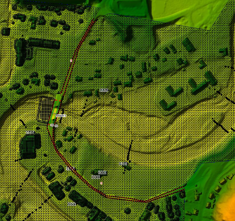
One thing that wasn’t obvious to me when I modelled my first bridge as a culvert with RAS2D was that I didn’t know which cells were considered for the culvert hydraulics calculation. I’ve found out there are only two cells even if the 2D area connector spans over many more: one upstream and one downtream. This is different from the weir flow calculation, which will take into account all the cells adjacent to the 2D area connector. Because only two cells are considered for culvert flow calculation, you should make sure to select a small time step or adapt the size of these two cells so that too much flow cannot travel from one cell to the other over a single time step. It’s easy to picture that things would go really wrong if the solver tries to compute the flow between two really tiny cells (say 0.1 * 0.1 m) based on a very large culvert (say 20m wide by 5m high). You’d need a super small timestep not to empty the upstream cell and not to generate super high flow depth at the downstream cell, otherwise there would obviously be some oscillations.
One trick to preserve small cells and a decent time step could be to model the bridge opening(s) with many culverts whose culmulated areas match with the bridge opening(s) area. I haven’t tested that out but I guess that it could work, in theory. The loss coefficients should certainly be adapted not to cumulate them.
-
AuthorPosts
- You must be logged in to reply to this topic.


