Welcome to the RAS Solution › Forums › HEC-RAS Help › 1D/2D Flow Exchange & Minimum Flow Tolerance
- This topic has 2 replies, 773 voices, and was last updated 7 years, 9 months ago by Scott Miller.
-
AuthorPosts
-
April 19, 2018 at 8:40 pm #6862Scott MillerParticipant
Foremost I would like to know what happens to 1D/2D flow error. The minimum flow tolerance in my model is 50 cfs, with up to 10 iterations. I have 1D/2D flow errors from 51 cfs to as much as 200 cfs. Is mass being conserved? The manual does not say, where minimum flow tolerance is described.
The purpose of the model is to evaluate flood extent and elevation in a small low gradient valley. The watershed extends east from a saddle point in the valley, through a marshy meadow that was ditched around 1900 (s ≈ 0.0015), to a natural channel (s ≈ 0.025) and a downstream confluence with a larger creek where a gauge was located.
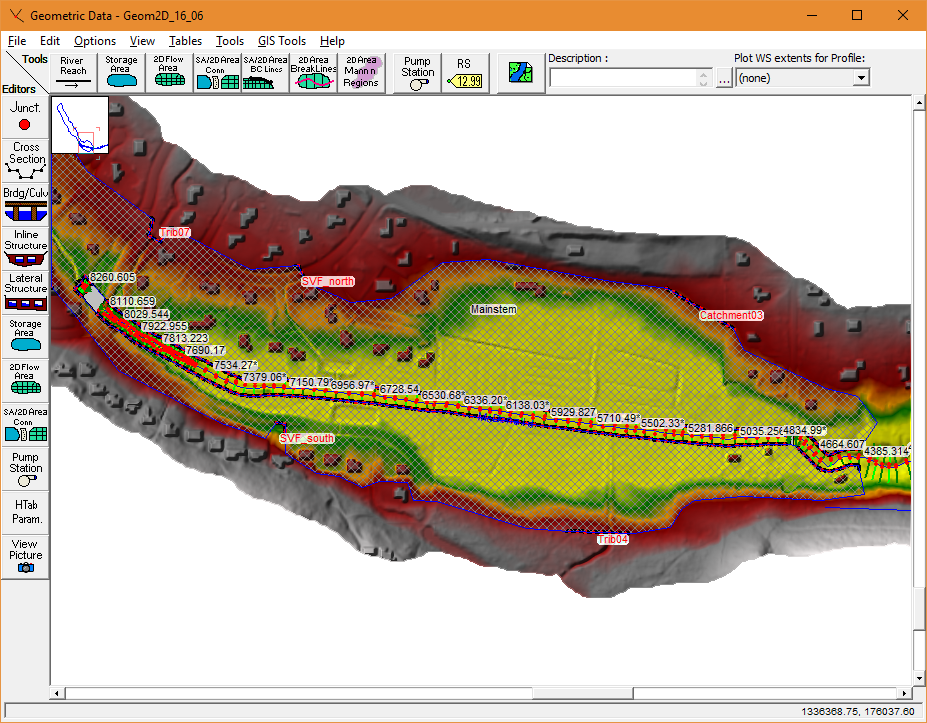
The hydraulic model extends from near the saddle point east to the larger confluence. The 2D area is at the head of the model and extends as far as the steeper natural channel. The 1D model extends from downstream at the confluence with the larger stream up the natural channel to the 2D area, and about 4000 feet into the 2D area. Changes to channel characteristics or culverts are being considered in the upstream reach of the 1D model. See geometry detail below.
There are eight lateral weirs along each bank of the water course connecting the 1D and 2D areas. They essentially span the entire length of the lateral interfaces, with consideration given to cell, cross section, and culvert locations. The terrain is fairly uniform, without many obvious high spots where flow exchange would not occur. Some of the lateral structures are several hundred feet long. Should I have made them shorter and more numerous? That may allow me to set the minimum flow tolerance lower.
April 19, 2018 at 11:09 pm #11335AnonymousGuestRegarding mass conservation:
The pdf’s from the 2D flow class that HEC puts on goes over this. I don’t know if those pdf’s are available for download or not. But anyway, for a given time step, the 1D is computed first and it computes a flow over the lateral structure. Say it is 1000 cfs. The 2D is computed second taking into account the flow over the lateral structure. With the newly computed water surfaces, on the 2D side, the flow over the lateral weir is re-computed, say it is 1050 cfs. Mass is conserved in that 1000 cfs of water is removed from 1D and 1000 cfs is added to 2D. The 50 cfs error is an error of hydraulic accuracy. If you view the computation log file, under options, it will report the mass balance error.
It can up your run time, but using a shorter time step can sometime help.
Where the lateral structure does not represent a high ground/levee but is rather just arbitrarily drawn, I have had success using the 2D domain option instead of 1D weir flow. I know at least one user on this site has reported rather mixed results with it so you will just have to try it.
Regarding breaking up the lateral weirs into smaller sections, I don’t know. It might help.
April 23, 2018 at 8:04 pm #11336Scott MillerParticipantThank you jarvus. I’ll check the mass balance error when this model finishes tomorrow. I’ll try a smaller time step (1s) after building a computer for 2D modeling. A two core laptop really doesn’t cut it.
-
AuthorPosts
- You must be logged in to reply to this topic.
