Welcome to the RAS Solution › Forums › HEC-RAS Help › 1D Profile Drops to Zero WSL & EGL along Lateral Weir 2D Connection – see im
- This topic has 6 replies, 481 voices, and was last updated 7 years, 10 months ago by Scott Miller.
-
AuthorPosts
-
March 30, 2018 at 3:12 am #6831Scott MillerParticipant
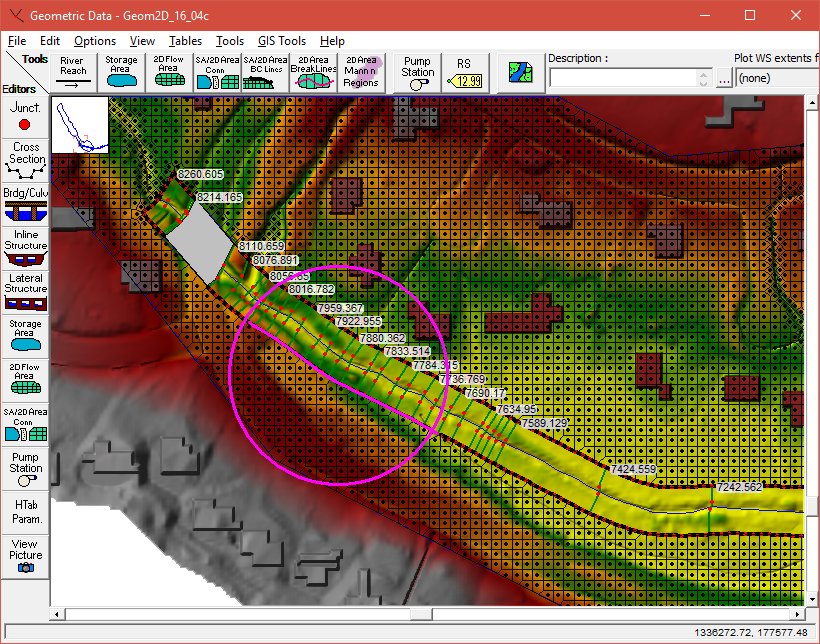
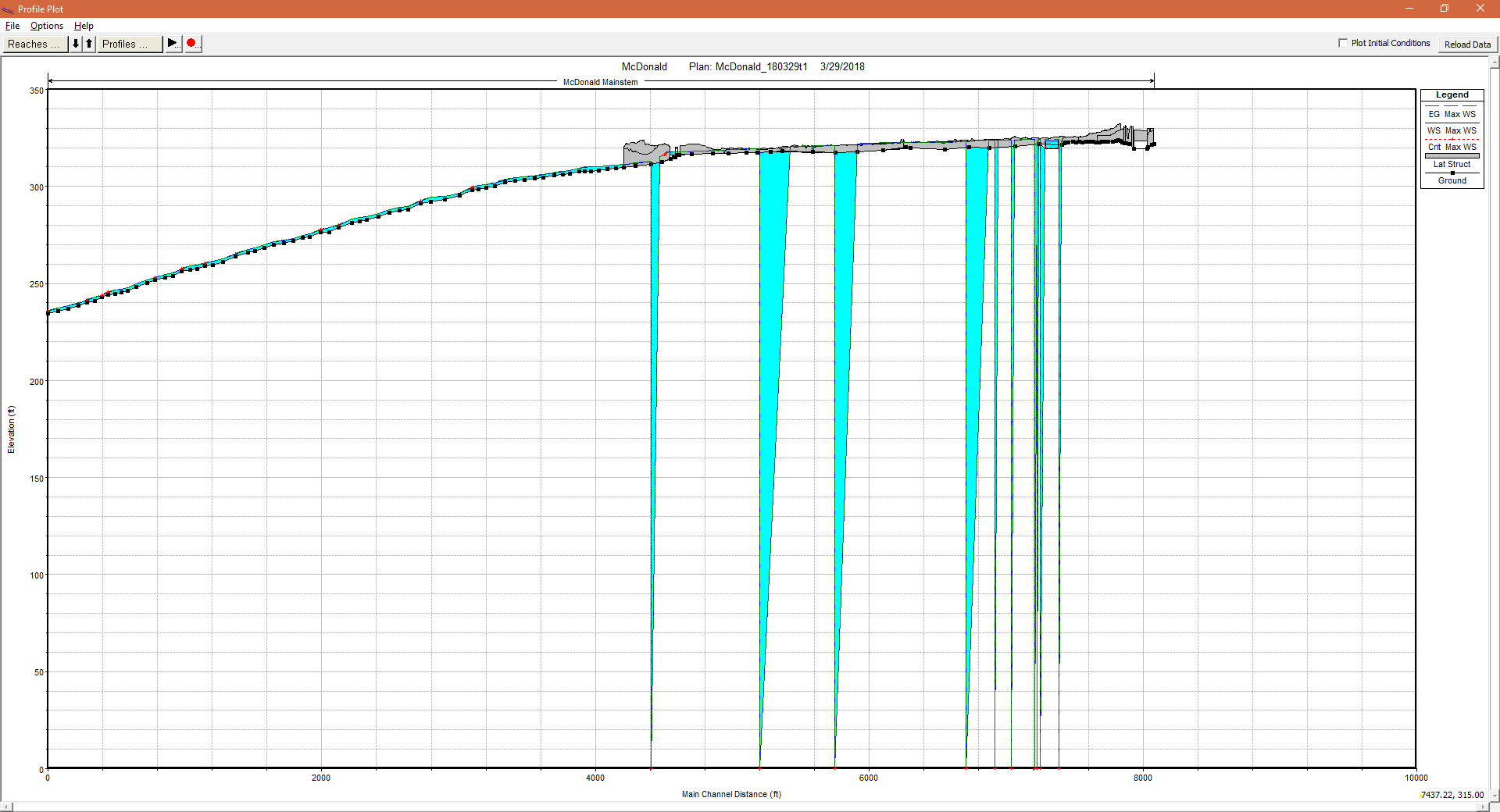
Hopefully you can see the image below. I’ll try to describe it in case you cannot.
I am modeling inundation in a low gradient valley using 1D/2D RAS. The 1D part is a uniform 70 feet wide corridor about 4000 feet long, wrapped within a single 2D area. I used GIS to buffer the stream alignment, and used that buffer line to define left and right boundaries between the 1D and 2D areas.
I also used the alignment of the buffer line to define centerlines of lateral structures – lateral weirs connecting the two areas using normal 2D equations, instead of weir equations. I raised the lateral structures 0.05 foot above the terrain, and made them only 0.01 foot wide. I do not anticipate that those dimensions matter. Overall there is little separation between the 2D and 1D areas.
The model is running stable on HEC RAS 5.0.3 with no warnings or errors. Nevertheless, the 1D profile is odd. At several places the water surface elevation and EGL are shown dropped to zero elevation. And they rise to reasonable looking values. Some of the cross sections are skipped this way and appear dewatered. The drop and rise are linear. I do not know if this is simply a rendition problem, or something getting lost in calculation. The mapper views look fine and complete.
In any case, the drops to zero appear to be associated with the lateral structures. Removing a lateral structure from the model can remove the drop. I have not figured out what this is. Please sound off if you recognize what may be going on.
March 30, 2018 at 9:22 pm #11277cameronParticipantDo you have the 1D/2D iteration option turned on? Try using the weir equation instead of the 2D equation for the weirs as this sometimes hides issues.
April 6, 2018 at 9:12 pm #11278Scott MillerParticipantI changed the method of calculating flows across the lateral structures from 2D equation to weir equation. When I did this I was not able to use the hot start file from the last run (which used 2D equation). The preprocessor said that the hot start file had a breach in the lateral structure plan. I’m not sure why. There were no breaches scheduled anywhere in the geometry when the model run started. This was my only clue as to what had been wrong with the lateral structures.
Changing to the weir equation stopped the leaks that showed in the profile plot. At that point it was a matter of stabilizing the 1D model, which had the tendency to go dry at its head before flow reached it through the 2D area. I got past this by putting an inflow near the head of the 1D model to flood the upstream 2D channel at a cold start. With that in place the only way I found to stabilize the 1D model was to iterate calculation of flow over the lateral structures. It took some testing to choose thresholds for minimum flow and number of iterations. Then it was necessary to find a time step sweet spot between stability of the 2D area and stability of the 1D model.
Overall the model is about 50 percent slower than when using 2D equation for the lateral structure, but it is stable and results look right.
May 25, 2018 at 7:28 pm #11279Scott MillerParticipantWith 5.0.4 I rebuilt the 2D area and lateral structures. Refinement regions made those scores of manually added calculation points a thing of the past. It was not strictly necessary to rebuild the lateral structures, but made sense to get them on about the same length scale. The minimum flow tolerance applies to them all equally.
Lengthening the lateral structures in a reach where flow goes rapidly overbank, and back, appeared to be the cause of new 1D model instability. It would have made sense to re-shorten the lateral structures in that reach. Instead, I first switched back from weir equation to normal 2D equation for the lateral structures. The model stabilized, and there were no phantom breaches anymore.
Maybe it helped that I lined up the head and tail ends of left and right bank lateral structures. Maybe it helped that I paid more attention to putting their ends near model cross-sections (non-interpolated). I don’t know. Maybe 5.0.4 works better for a reason I’m unaware of. In any case the model is faster and smoother.
May 29, 2018 at 5:06 pm #11280AnonymousGuestIs flow entering through the 1D reach with options to overflow to the 2D area?
Or is flow coming from the 2D area into the 1D area? Or is flow entering both (i.e.) hydrograph on the reach and precipitation in the grid?May 29, 2018 at 7:41 pm #11281AnonymousGuestMake sure your weir coefficient is between 0.2 to 0.5. This drastically changes results. I asked the previous question because if water is transferring from the 2D area to the 1D cross section, remember the transfer of flow appears automatically in the channel of the cross section, it will not travel through the overbanks.
June 4, 2018 at 8:25 pm #11282Scott MillerParticipantThank you Luis.
I see the section on Lateral Structure Weir Coefficients in the 2D Modeling Users Manual. For the case where I am using lateral structures to connect 1D channel to 2D overbanks, the default weir coefficient, 2, is much too high. Good tip.
Chris Goodell makes some helpful points in his response to Toby in this post: http://hecrasmodel.blogspot.com/2016/07/weir-equations-in-hec-ras.html
The phantom breaches in my model do not appear anymore. It is a mystery what caused them.
-
AuthorPosts
- You must be logged in to reply to this topic.

