February 20, 2025
Full Momentum Episode 37: All Things Gates
Gates play a crucial role in hydraulic modeling, impacting water flow, flood control, and dam operations.
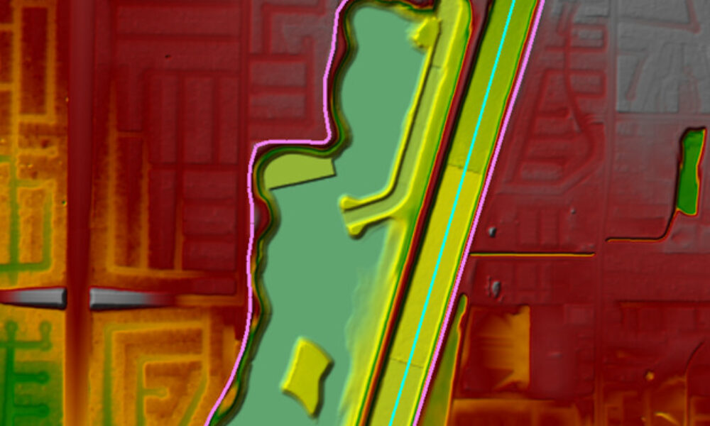
Lateral structures can be used in HEC-RAS for transferring flow from a river/reach to another river/reach, 2D area or storage area. This allows the user to physically represent a variety of geometric features. In this example, lateral structures were used to capture flow overtopping high ground on the spine of a sharp river bend in a 1D model (Figure 1).
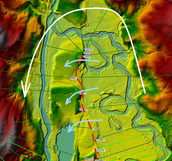
Figure 1. River bend showing flow short-circuiting the bend during high flow conditions.
During low flow conditions, flow remains in the channel and follows the channel alignment around the bend as shown with the white arrow in Figure 1. During high flow conditions, flow in this area is two-dimensional, with flow transferring from the upstream side of the bend (right side) to the downstream side of the bend (left side) over the spine of the bend, represented by the red dashed line. One option for simulating this in HEC-RAS would be to convert this part of the reach to a 2D area, but in this case we wanted to keep the model 1D (to keep the model simple and fast!). In a 1D HEC-RAS model, when the water surface elevation exceeds the elevation of the cross-section terrain, the cross section is extended vertically from the end creating a “wall” at the edge of the cross section (see figure below). In this case, this limits flow from transferring from the upstream end of the bend to the downstream end through the center high ground that is overtopped in the high flow scenario. This forces flow around the bend in the channel, not allowing it to short circuit the bend. In reality, flow would be transferring from the upstream end of the bend to the downstream end of the bend, resulting in a much smaller drop in head moving across the spine of the bend.
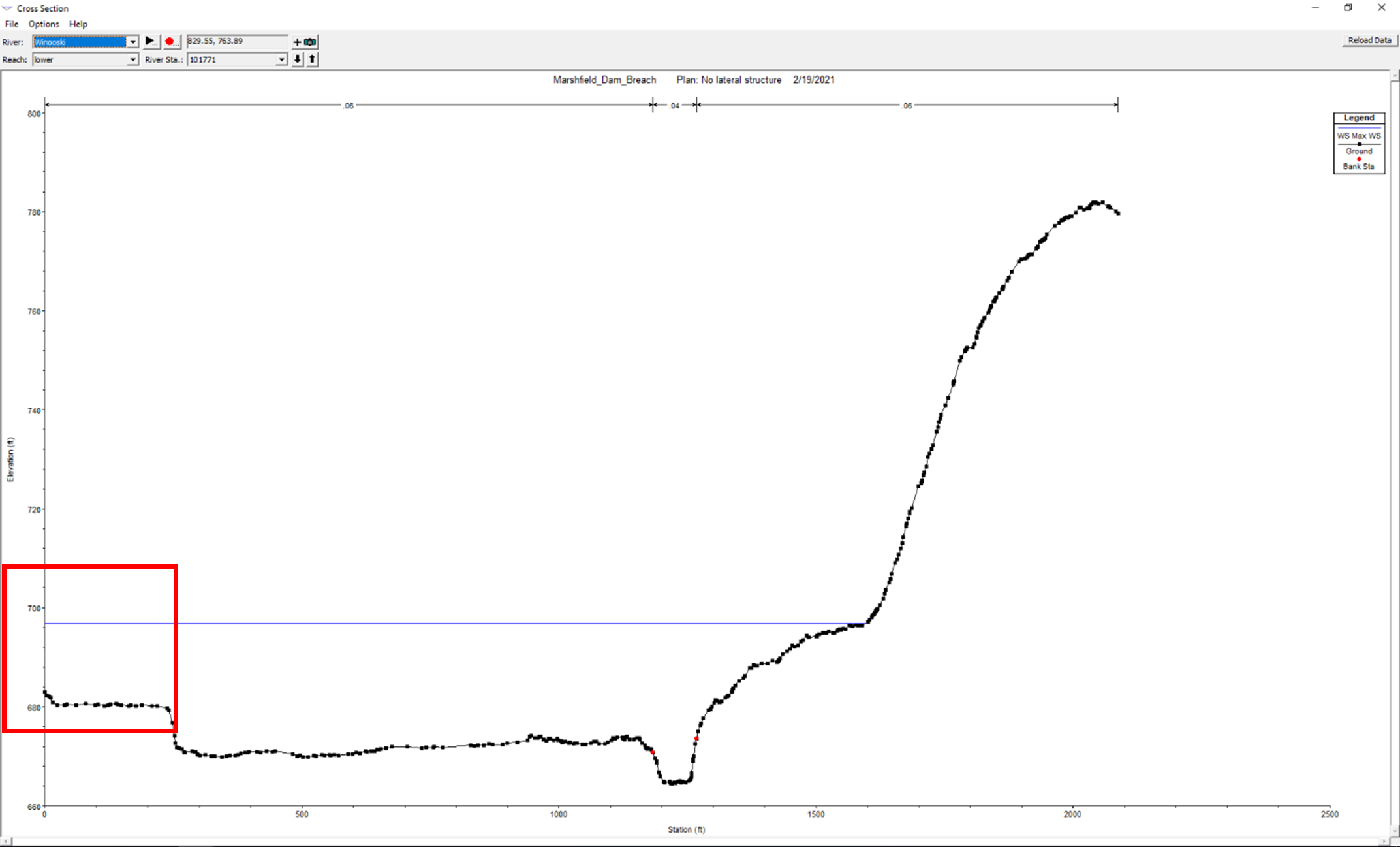
Figure 2. Water surface elevation exceeds the cross section end points on the left.
In order to keep the model 1D while still accurately capturing the transfer of flow through the spine of the bend, a lateral structure was used to connect the upstream portion of the bend to the downstream portion of the bend. So in this case, the headwater and tailwater references for this lateral structure are the same river. There are some specific limitations however when connecting a reach to itself using a lateral structure. In this case, for both the upstream and downstream end of the bend, the lateral structure must be connected to the left overbank. You cannot simply use a georeferenced lateral structure to connect the upstream cross sections to the downstream cross sections as one would assume. HEC-RAS is unable to recognize that the tailwater connections should be decreasing in weir stationing heading downstream and thus a single lateral structure cannot be used to transfer flow to the downstream end of the bend. Instead, multiple lateral structures must be used to differentiate flow transferring to sets of cross sections on the downstream end. The lateral structure must be split into multiple smaller lateral structures that extend between the downstream cross sections (Figure 3).
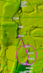
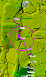
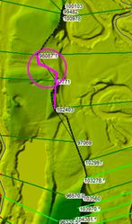
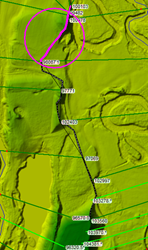
Figure 3. Lateral structure split into four smaller lateral structures.
Splitting the lateral structure allows each lateral structure to deliver flow to a set of cross sections by assigning the tailwater flow to go to “a point between two XS’s”. Here we set up the multiple lateral structures so that each one only delivered flow between 2 cross sections. Each lateral structure will deliver flow between its specified cross sections, transferring flow across the downstream cross sections. When you compare the results across the lateral structure and both the upstream and downstream end of the bend, you see that without the lateral structure there is a significant backwater behind the bend (upstream) and a lower WSE on the downstream end (Figure 4). With the lateral structure in place, the energy gradient is reduced significantly and results in a more reasonable water surface profile in this area. Since the lateral structure uses the weir equation, it is important to select a weir coefficient that minimizes the head drop over the spine of the bend. For this example, we used a weir coefficient of 1.2 for each of the four lateral structures. While traditionally we think of weir coefficients in the 2.5 to 4 range, using the weir equation to simulate overland flow requires a smaller coefficient. This post by Chris Goodell includes a good explanation of weir coefficients for different applications. But be careful not to use a weir coefficient that is too low, as the head drop over the weir could be too great. Of course the amount of head drop is subjective so consider a sensitivity analysis and calibration if possible.
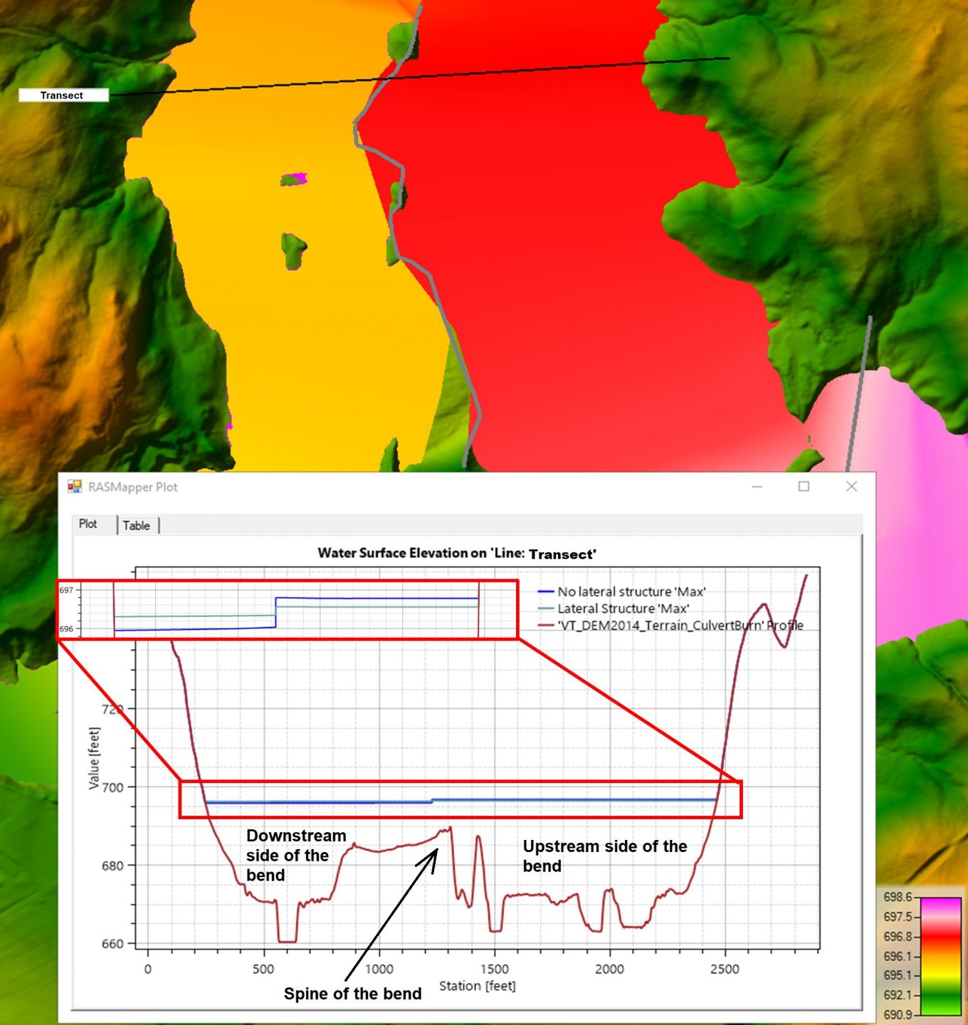
Figure 4. Differences with and without lateral structure on the bend.
Still, a strong argument could be made to make this portion of the model a 2D area and let HEC-RAS figure out the flow transfer around the bend and over the high ground at the spine of the bend-especially considering the uncertainty of the weir coefficient to use. But if you do have to keep the model 1D, this would be a suitable method to simulate this effect.
Comments
Mohammad Aemal Umar
on May 7, 2021Is its possible to analysis and model the retaining-wall as “Lateral Structure” for roadway embankment protection.
Michael K.
on May 27, 2021Would this solution yield a reasonable result in a steady flow model?
Chris Goodell
on May 27, 2021It would be very tricky to do this in steady flow because of needing to use the split flow optimization feature. I wouldn’t expect it to work. Better to run an unsteady flow model and ramp up to a constant discharge, holding it long enough to achieve a “steady state” solution.
Michael K.
on July 1, 2021I see, thanks for the feedback!
Are there any good resources for learning the details of the lateral structure computations and split flow optimization?
Chris Goodell
on July 2, 2021Specifically, I’m not aware of any resources that directly address this other than the manuals. You might do some searching in The RAS Solution posts and forum, or one of the social media forums.
Add Your Comment